Cooling device and method for intraoral device illumination source

a cooling device and illumination source technology, applied in the field of dental appliances, can solve the problems of difficult illumination of the interior of the mouth of a dental patient during dental examination and/or operation, limited amount of light entering the oral cavity using this type of lighting, and limited light directed only on a limited area in the mouth

Inactive Publication Date: 2007-10-30
INNERLITE
View PDF33 Cites 41 Cited by
  • Summary
  • Abstract
  • Description
  • Claims
  • Application Information

AI Technical Summary

Problems solved by technology

Illuminating the interior of a dental patient's mouth during dental examination and / or operation is difficult because the patient's mouth must be illuminated through a narrow opening, i.e., the patient's mouth, and the dental operator must work in close proximity to the mouth, often blocking the light source.
The amount of light entering the oral cavity using this type of lighting is somewhat limited due to the fact that the light source is remote from the patient's mouth.
However, this type of lighting has a number of drawbacks.
Light is only directed on a limited area in the mouth and does not provide illumination for the entire oral cavity.
Additionally, the presence of this type of lighting, typically as an add-on feature on the instrument interferes with the comfortable and proper use of the instrument.
Other devices have been designed specifically for illuminating a patient's teeth, but these devices suffer from any or all of the following drawbacks: inadequate illumination of the patient's teeth, and interference with other dental instruments used during the examination and / or operation.
A problem with the use of LED(s) or other illumination sources in this manner is that these illumination device(s) emit heat, which can damage the device or accessories and be uncomfortable or hazardous for the patient.

Method used


Image

  • Cooling device and method for intraoral device illumination source
  • Cooling device and method for intraoral device illumination source
  • Cooling device and method for intraoral device illumination source

Examples


Embodiment Construction

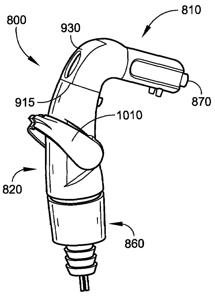
[0045]An aspect of the invention involves a combined illumination, aspiration and heat sink device for use with an intraoral illumination device. Before describing the combined illumination, aspiration and heat sink device, a number of embodiments of intraoral illumination devices, which represent other aspects of the invention, will first be described.

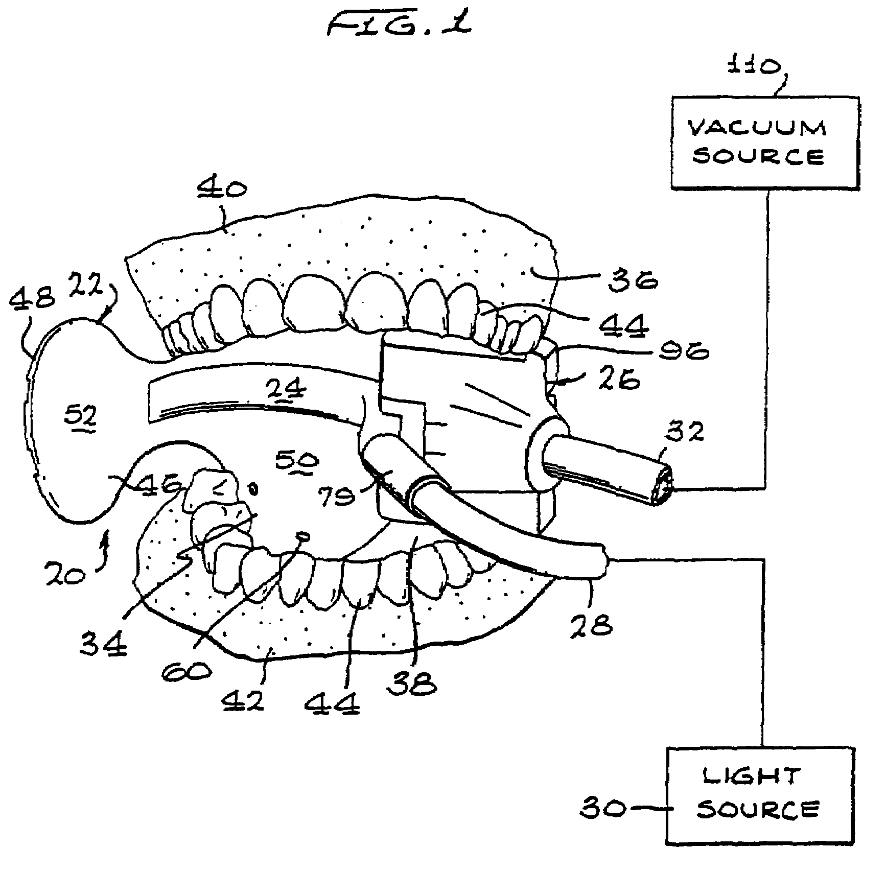
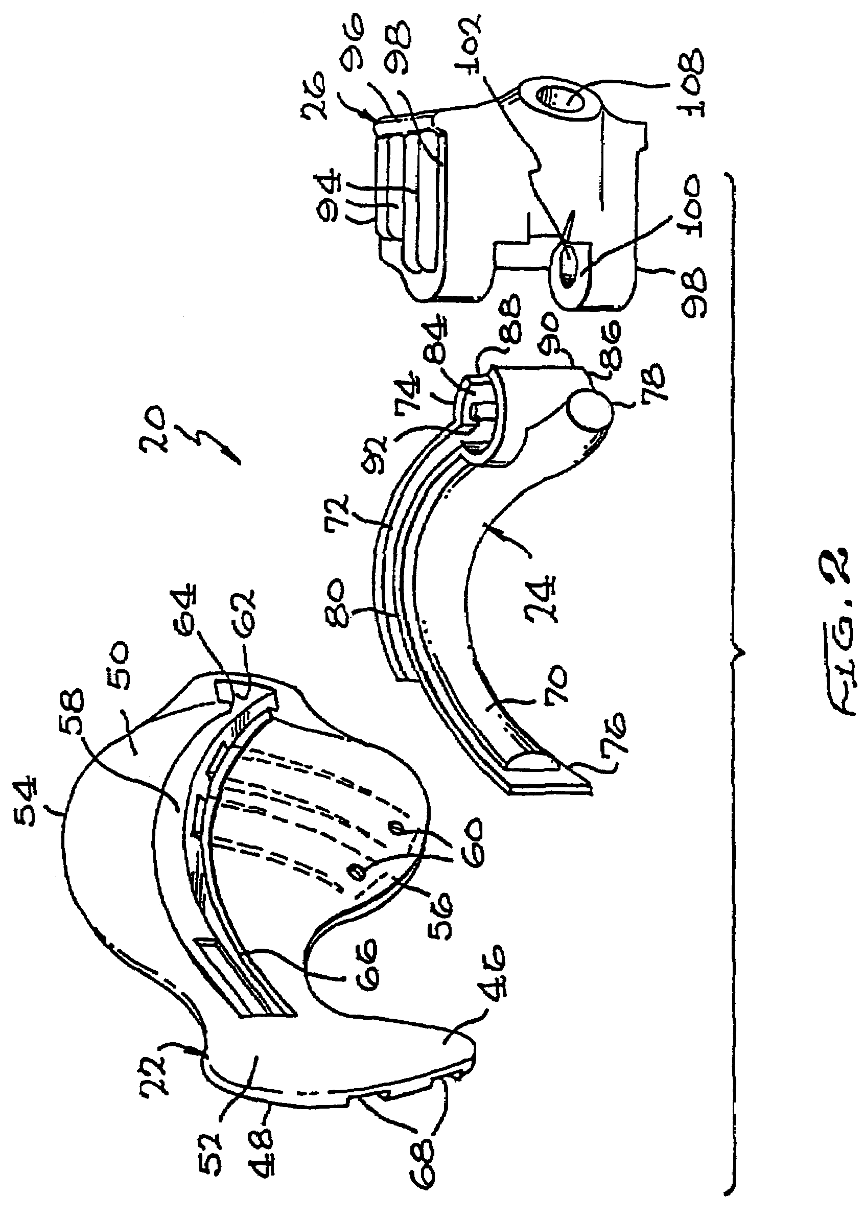
[0046]With reference to FIGS. 1 and 2, an embodiment of an intraoral illumination device, indicated generally by the reference numeral 20, will now be described. The intraoral illumination device 20 generally includes a tongue and cheek retractor 22, a dispersion piece 24, and a bite block or piece 26. The tongue and cheek retractor 22 is a disposable piece, and the dispersion piece 24 and bite piece 26 are sterilizable for reuse. In an alternative embodiment, the entire intraoral illumination device 20 is disposable. The dispersion piece 24 is coupled to a light carrier such as a fiber optic bundle 28 and extraoral light source 30 fo...


PUM


Abstract

A method of using a heat sink device with an intraoral illumination device includes inserting an intraoral illumination device at least partially in a patient's mouth, connecting a heat sink device to the intraoral illumination device, the heat sink device including an illumination device that emits light and heat when activated and a heat sink member thermally coupled to the illumination device; activating the illumination device so that light is transmitted to the intraoral illumination device and into the patient's mouth, aspirating fluid from the patient's mouth at negative pressure; and causing aspirated fluid to flow past the heat sink member at negative pressure so that heat is removed from the heat sink member, causing the illumination device to be cooled.

Description

CROSS-REFERENCE TO RELATED APPLICATIONS[0001]This is a continuation-in-part of prior application Ser. No. 10 / 375,230 filed Feb. 27, 2003 now U.S. Pat. No. 6,974,321, which is a continuation-in-part of prior application 10 / 006,732 filed Nov.15, 2001, which issued on Jun. 10, 2003 as U.S. Pat. No. 6,575,746, which is a continuation of prior application Ser. No. 09 / 777,491 filed Feb. 5, 2001 which issued on Jan. 15, 2002 as U.S. Pat. No. 6,338,627, which is a continuation of prior application Ser. No. 09 / 490,923 filed on Jan. 25, 2000, now abandoned, which is a continuation of prior application Ser. No. 09 / 193,916 filed on Nov. 17, 1998, which issued on Feb. 8, 2000 as U.S. Pat. No. 6,022,214.FIELD OF THE INVENTION[0002]The invention relates to dental appliances for illuminating and / or vacuum suction of the mouth, and accessories and methods therefor.BACKGROUND OF THE INVENTION[0003]Illuminating the interior of a dental patient's mouth during dental examination and / or operation is diff...

Claims


Application Information

Patent Timeline
Patent Type & Authority Patents(United States)
IPC IPC(8): A61C1/00A61C17/14A61C17/06A61C17/08
CPCA61C1/088A61C17/043A61C17/04A61C5/14A61C5/90A61C17/08A61C17/084A61C17/10A61C17/13
Inventor HIRSCH, JAMES A.
Owner INNERLITE
Why Eureka
Try Eureka