Piezoelectric resonator element, piezoelectric resonator, and piezoelectric oscillator

a piezoelectric resonator and piezoelectric technology, applied in piezoelectric/electrostrictive/magnetostrictive devices, piezoelectric/electrostrictive/magnetostrictive devices, piezoelectric/electrostrictive/magnetostriction machines, etc., can solve problems such as structural problems and ablation of vibration, and achieve enhanced suppression of vibration, prevent electrical characteristics of main vibration, and suppress thickness shear vibration propagation

Inactive Publication Date: 2007-11-27
SEIKO EPSON CORP
View PDF17 Cites 35 Cited by
  • Summary
  • Abstract
  • Description
  • Claims
  • Application Information

AI Technical Summary

Benefits of technology

[0009]In the piezoelectric resonator element of the invention, placing a plurality of grooves to be in enclosure-like shapes surrounding the center portion of the main surface causes gradual dampening of the thickness shear vibration from the center portion toward the outer peripheral portion of the main surface in every direction of the resonator element. It therefore becomes possible to prevent electrical characteristics of the main vibration from being affected by abrupt dampening of the vibration and therefore to secure a frequency variable range.
[0017]Providing a piezoelectric resonator that includes the above described piezoelectric resonator element according to the invention, and a holding portion fixing and connecting the piezoelectric resonator element becomes possible.

Problems solved by technology

According to the structure indicated in the above background, however, providing a groove outside the excitation electrode results in abrupt dampening of the vibration in the closest proximity to the vibration region of the resonator element.
The structure therefore has problems.

Method used


Image

  • Piezoelectric resonator element, piezoelectric resonator, and piezoelectric oscillator
  • Piezoelectric resonator element, piezoelectric resonator, and piezoelectric oscillator
  • Piezoelectric resonator element, piezoelectric resonator, and piezoelectric oscillator

Examples


first embodiment

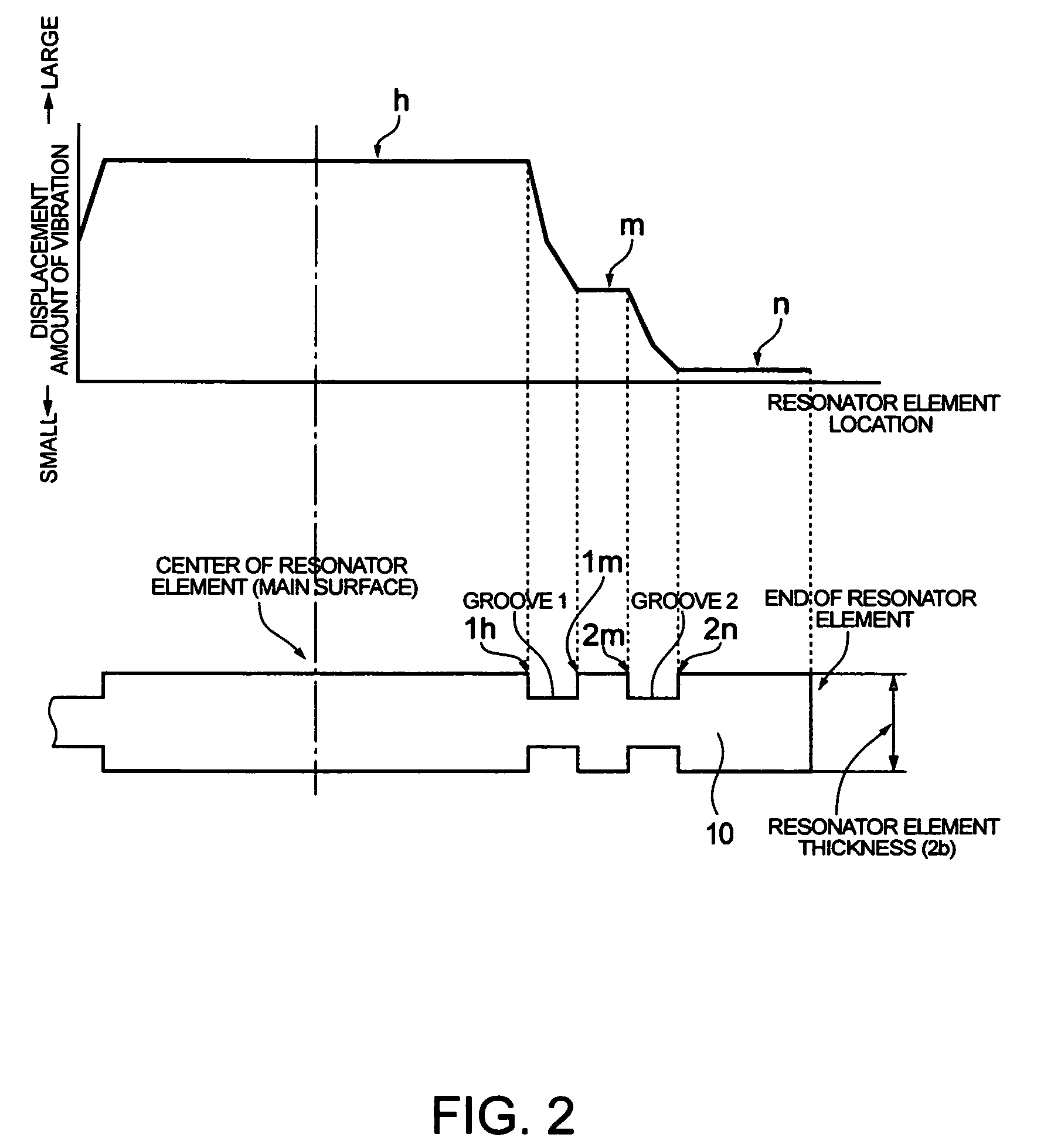
[0050]Damping of the thickness shear vibration of the resonator element by the use of a plurality of grooves of the first embodiment will be now described by using FIG. 2. FIG. 2 is a diagrammatic view showing dampening of the thickness shear vibration, which is the main vibration of the resonator element. Incidentally, in the exemplary embodiment, an example of dampening the thickness shear vibration by two grooves up to the displacement amount of the vibration with which characteristics of the thickness shear vibration, which is the main vibration, are not affected even though the outer peripheral portion of the resonator element is held will be described.

[0051]According to FIG. 2, the thickness shear vibration has the largest amount of displacement (h) in the center portion of the resonator element 10. The vibration is damped by the grooves 1 and 2 placed in the resonator element. Dampening of the thickness shear vibration begins from the inner peripheral side edge (1h) of the gr...

fourth embodiment

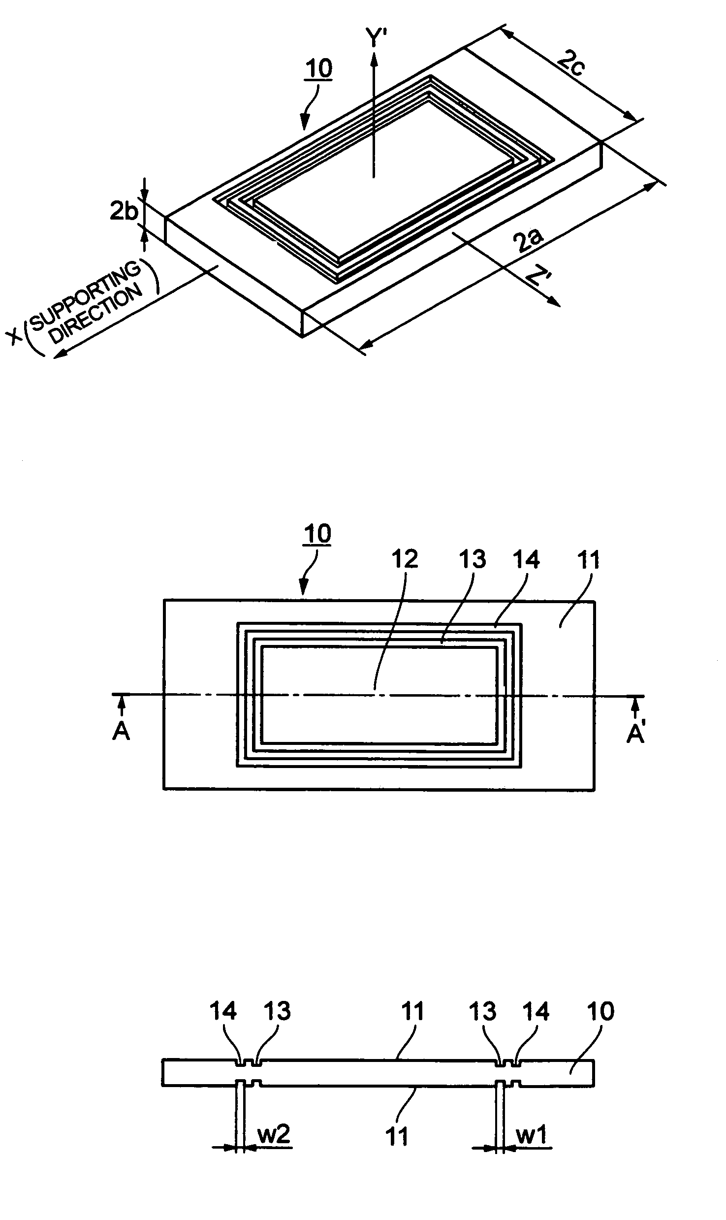
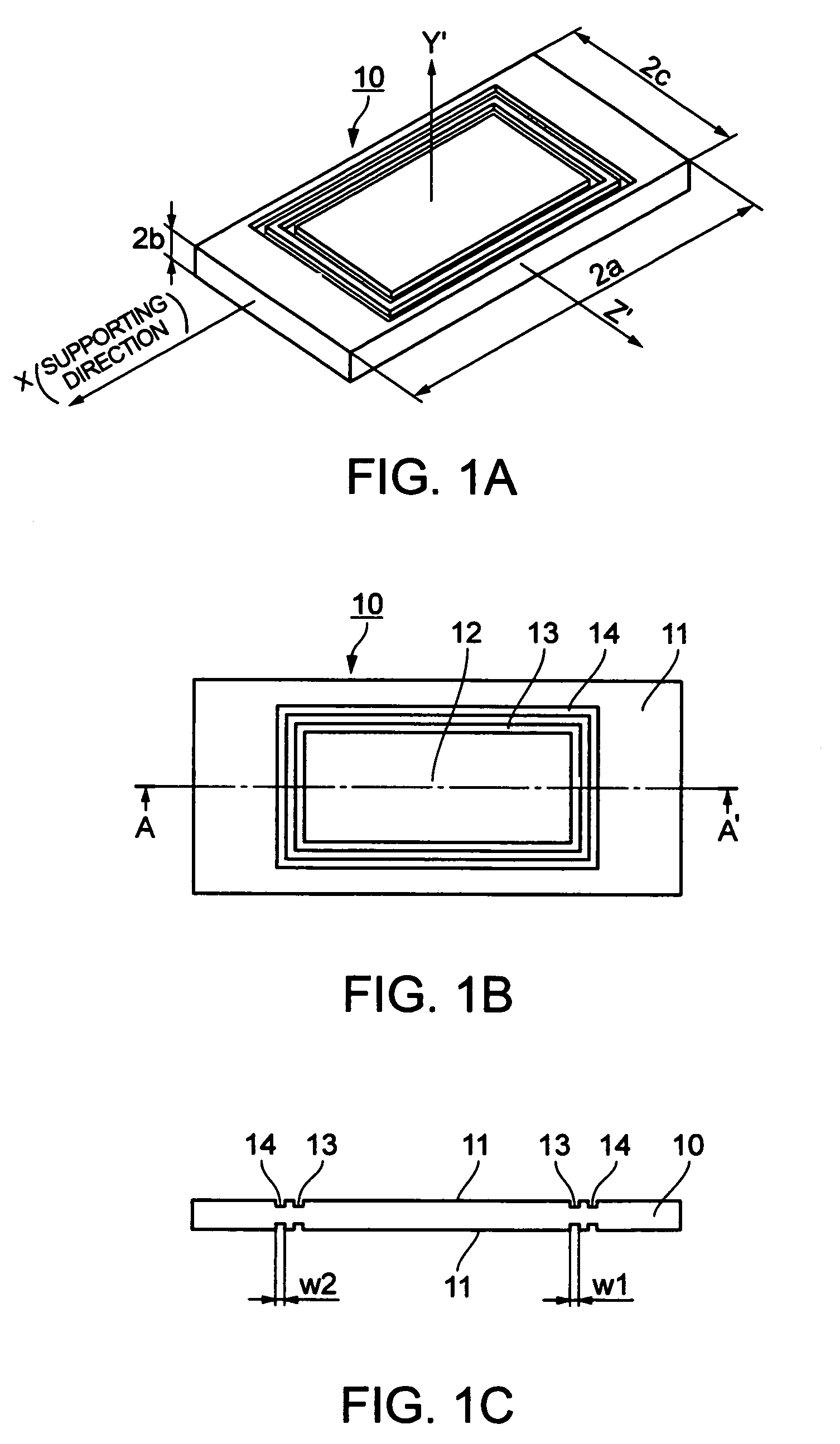
[0073]The resonator element having the groove width larger than the thickness of the resonator element as an exemplary embodiment of the piezoelectric resonator element of the invention will be described by the use of FIGS. 10A, 10B, and 10C. FIGS. 10A, 10B, and 10C are schematic views of the resonator element for explaining a fourth embodiment, where FIG. 10A is a perspective view of the resonator element, FIG. 10B is a plan view of the resonator element, and FIG. 10C is a sectional view taken along lines A-A′ of FIG. 10B.

[0074]A piezoelectric substrate having a groove with a predetermined grove width on the main surface will be described using an AT cut quartz crystal resonator element 41 having the resonance frequency of 27 MHz, the fraction of the X side of 33, and the fraction of the Z side of 21 as an example. The Y′-axis and the Z′-axis of the resonator element 41 of the embodiment correspond to new coordinate axes made by rotating clockwise at 35.25 degrees in the +X directi...


PUM


Abstract

Aspects of the invention provide piezoelectric resonator element having a plurality of grooves for suppressing propagation of the thickness shear vibration from the center portion to the outer peripheral portion of the main surface being placed in enclosure-like shapes surrounding the center portion of at least one of the main surfaces.

Description

BACKGROUND OF THE INVENTION[0001]1. Field of Invention[0002]Aspects of the invention relate to the shape of a piezoelectric resonator element for preventing a thickness shear vibration, which is the main vibration, from being propagated to the outer peripheral portion of the piezoelectric resonator element.[0003]2. Description of Related Art[0004]Regarding a thickness shear vibration, which is the main vibration of an AT cut quartz crystal resonator, although the placement of an excitation electrode is decided so that the center portion of the resonator element oscillates, the thickness shear vibration oscillating in the center portion can be propagated to the outer peripheral portion of the resonator element.[0005]The resonator element is held by fixing the outer peripheral portion of the resonator element to a housing made of ceramic or the like, and the propagated vibration can be suppressed because of fixing. This suppression of the propagated vibration has an effect on the thic...

Claims


Application Information

Patent Timeline
Patent Type & Authority Patents(United States)
IPC IPC(8): H03H9/54H01L41/08H03H9/15
CPCH03H9/02086H03H9/1021H03H9/19
Inventor TANAKA, MASAKO
Owner SEIKO EPSON CORP
Why Eureka
Try Eureka