
Terminal design with shock isolation assembly

a terminal design and shock isolation technology, applied in the field of portable electronic units, can solve the problems of increasing the weight of the unit by the same factor, affecting the stability of the unit, so as to prevent damage to electronic components, dampen an external mechanical shock, and dampen gradual effect of external mechanical shock

Active Publication Date: 2007-03-27
SYMBOL TECH LLC
View PDF9 Cites 35 Cited by
  • Summary
  • Abstract
  • Description
  • Claims
  • Application Information

AI Technical Summary

Benefits of technology

Significantly reduces mechanical stress on circuit components and solder joints, minimizing damage from external shocks and vibrations, while enabling modular design and cost-effective manufacturing through a 'build to order' process.

Problems solved by technology

In particular, many electronic units such as hand held mobile terminals, communication units, and the like are generally susceptible to damage during employment in harsh environments.
Consequently, whenever such unit is subject to shock or vibration from an external source, the printed circuit board may be damaged if the external shock is directly transmitted to it.
Such deceleration typically causes the weight of the unit to increase by the same factor as the acceleration in a short period of time.
For circuit boards, a deceleration of this magnitude will destroy the bonding between the related semiconductor chips and its board.
Another problem associated with such levels of acceleration or deceleration is that the printed circuit board may experience a significant deflection, since it is generally supported on its edges as a simple supported beam.
Such deflection, if severe, can in turn exert bending and torsional forces on various components mounted on the printed circuit board and damage the electronic unit.
This approach has the disadvantage of increasing the weight of the equipment, and the full effect of the increase in an “area moment of inertia” feature is not realized.
Moreover, since printed circuit boards typically are plated-through holes, the maximum thickness of the boards is limited by the practicality of obtaining such holes.
However, conventional methods of shock isolations have been focused only on shock mounting isolations for units only at one level, e.g. external mounting, or for a particular component of the unit, e.g. a display or a circuit board, and not to a total and integrated approach.
Moreover, mounting a printed circuit board by employing a simple spring-biased suspension between it and the chassis of the article will not entirely solve the problem of protecting the printed circuit board from potential damage from shock and vibration.
A major reason for this involves unstable mechanical support coupled with undesirable persistence of suspension vibration.
Shock or vibration delivered by an external source to the chassis of the article will be transmitted to the spring-biased suspension resulting in suspension vibration of a particular frequency and amplitude that in time will strain the substrate of the printed circuit board, leading to its eventual failure.
Another reason that a simple spring-biased mounting for a printed circuit board is not desirable is that suspension vibration will in time cause failure of the electrical leads connecting to the printed circuit board from elsewhere in the electronic unit.

Method used


Image

  • Terminal design with shock isolation assembly
  • Terminal design with shock isolation assembly
  • Terminal design with shock isolation assembly

Examples


Embodiment Construction

[0026]The various aspects of the present invention will now be described with reference to drawings. The invention provides for a system and methodology of isolating a portable electronic unit from external mechanical shocks and / or vibrations, so that the shock energy is significantly absorbed, and reduced to an acceptable safe limit by the time it reaches the electronic components.

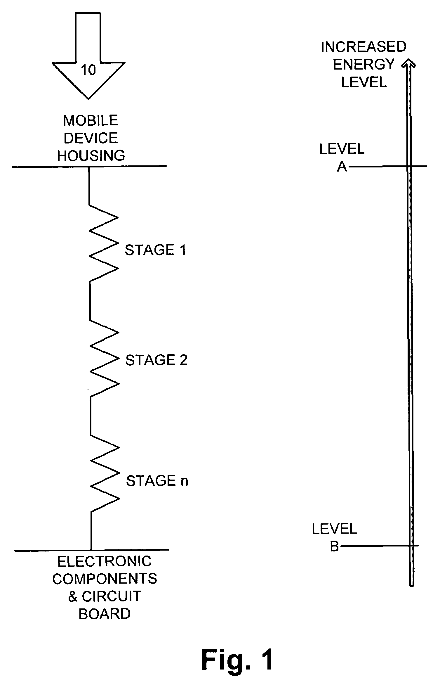
[0027]Referring initially to FIG. 1, an exemplary model that depicts one aspect of the subject invention is illustrated. A mobile unit is subjected to an external force as depicted by arrow 10. The mobile unit can be any hand held device with its internal electronic component, such as a circuit board with a Central Processing Unit (CPU) enclosed within a housing. The external force 10 can be induced via a mechanical shock, for example by dropping the unit on a hard surface.

[0028]Level A on the vertical energy axis depicts a level of energy created by external force 10 that can not be tolerated by the elec...


PUM


Abstract

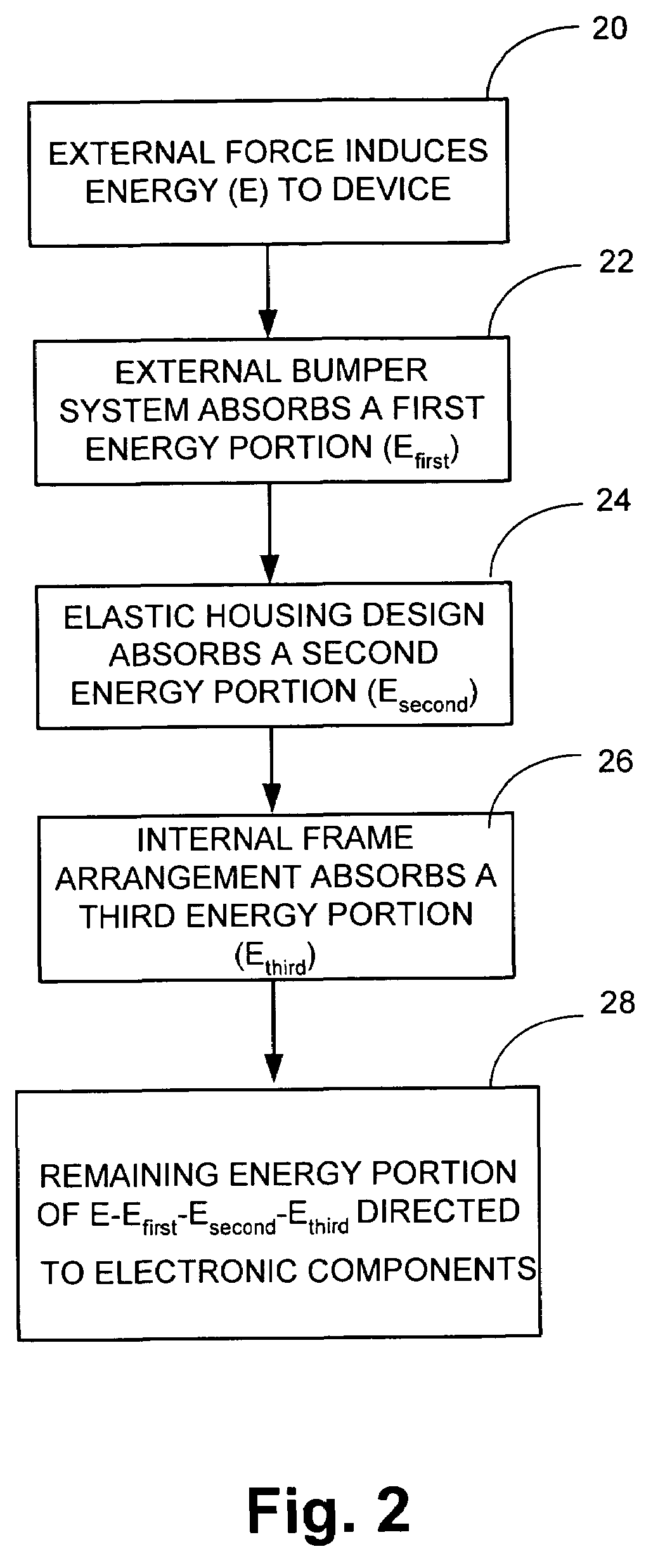
Systems and methodologies are disclosed for isolating a portable hand held electronic unit from external mechanical shocks and / or vibrations by dampening them at several levels. The system can absorb an external mechanical shock at three different levels by employing an external bumper system, elastic housing design features, and an internal frame isolation. Moreover, such isolation assembly simplifies production of the portable electronic unit by enabling a “build to order process” according to a customer's specification.

Description

FIELD OF THE INVENTION[0001]The invention described below generally relates to systems and methods of shock isolation for a portable electronic unit, and in particular to an isolation assembly employing several stages of energy absorption for dampening an external mechanical shock.DESCRIPTION OF THE RELATED ART[0002]Typically there is a desire to increase the ruggedness for electronic units, while lowering associated assembly costs and improving overall function. In particular, many electronic units such as hand held mobile terminals, communication units, and the like are generally susceptible to damage during employment in harsh environments. Such units are generally assembled by enclosing internal electrical components, such as a central processing unit (CPU) board, display, keyboard, and internal wiring, within a housing made of plastic or another structural material. The enclosure normally serves as a protective measure and is typically formed in two parts having an upper housin...

Claims


Application Information

Patent Timeline
Patent Type & Authority Patents(United States)
IPC IPC(8): G06K7/10G06F1/16G06K9/22
CPCG06F1/1626G06K7/10881G06F1/1684G06F1/1656
Inventor WULFF, THOMAS
Owner SYMBOL TECH LLC
Learn More