Compound archery bow construction and methods of making and operating the bow

a technology of compound archery and construction methods, applied in the field of compound archery bow construction and methods of making and operating the bow, can solve the problems of unbalanced torque and flex stress on the upper and lower limbs of the bow, and the noise of the game, so as to achieve a better balanced bow, less torqueing stress, and more accurate

Inactive Publication Date: 2007-12-18
WHEELER MARK G
View PDF12 Cites 55 Cited by
  • Summary
  • Abstract
  • Description
  • Claims
  • Application Information

AI Technical Summary

Benefits of technology

[0004]The present invention, in one aspect thereof, is concerned with the manner of mounting the resilient limbs to the handle riser as well as to the vertically centered alignment of the pulleys mounting the bow string along with the handle, and the positioning of the bow rest to achieve a vertically centered arrow relationship. This permits the archer to utilize a better balanced bow which is more accurate. Because of the balanced relationship achieved, the archer is presented with less torqueing stresses in the bow and less vibration is transferred via the bow limbs upon limb recoil and arrow release. Moreover, the positioning of the arrow in vertically centered position provides equal torque and flex forces on the limbs to generate more stored energy as the bow string is drawn. Another aspect of the invention is the provision of eccentric pulley assemblies, which aid in achieving these desired characteri

Problems solved by technology

One of the problems with achieving accuracy has been the recoil vibration occurring as the arrow is released from the bow, which has resulted also in undue noise that startles the game.
Another factor affecting accuracy is the alignment of the bow string which in the past has not prov

Method used


Image

  • Compound archery bow construction and methods of making and operating the bow
  • Compound archery bow construction and methods of making and operating the bow
  • Compound archery bow construction and methods of making and operating the bow

Examples


Embodiment Construction

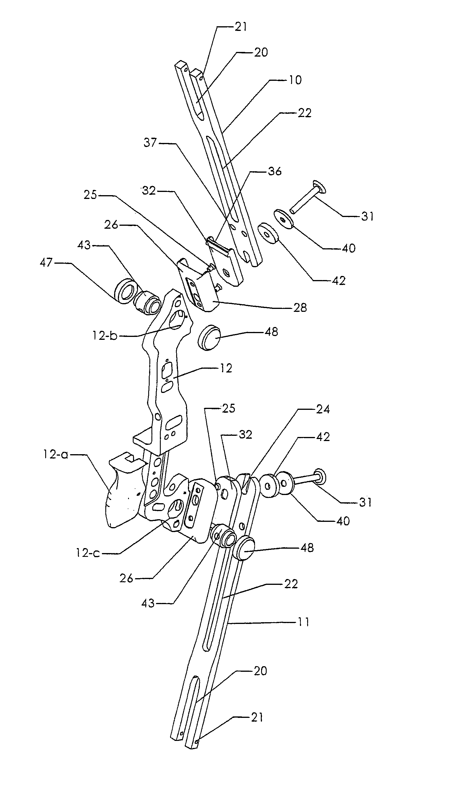
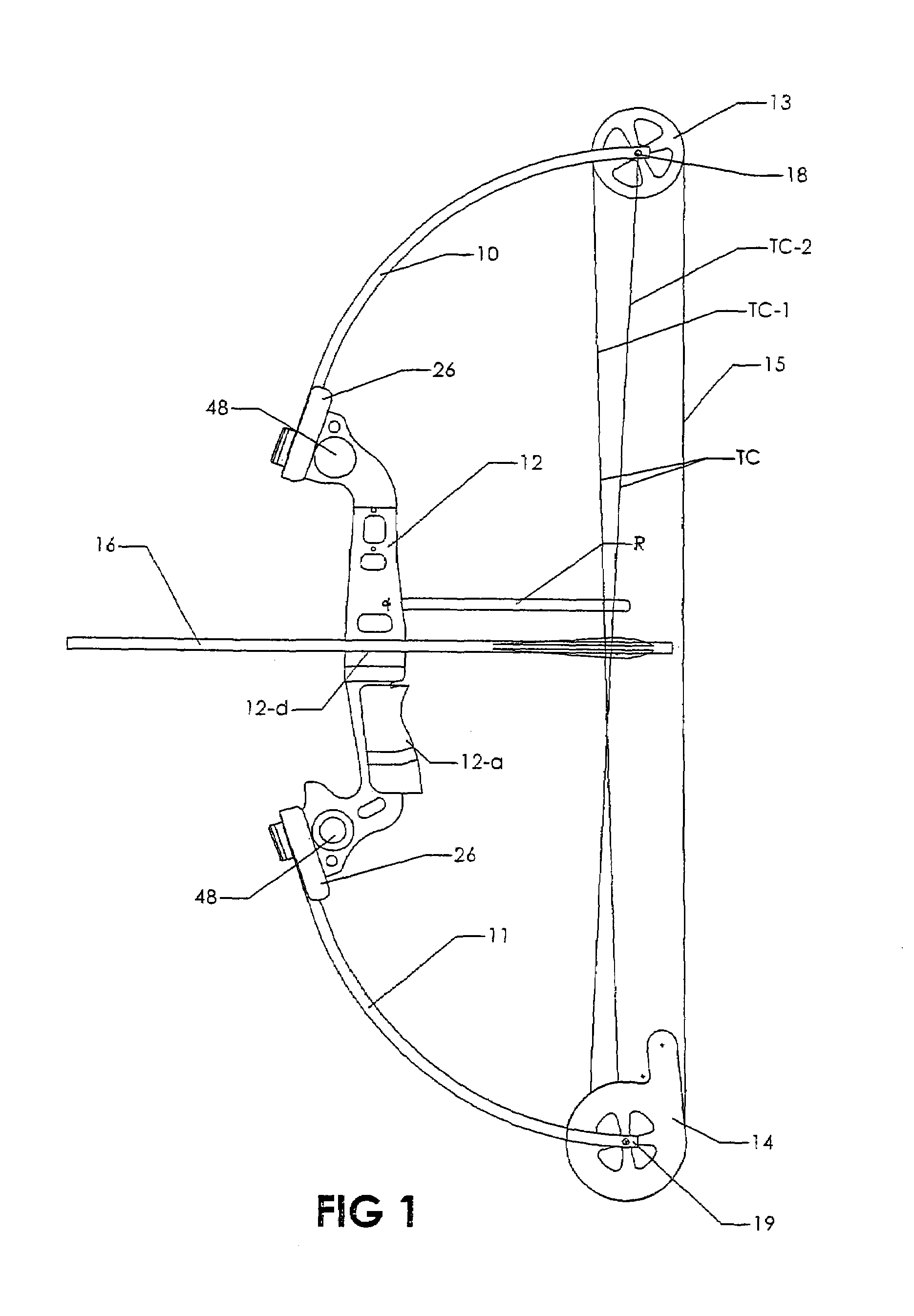
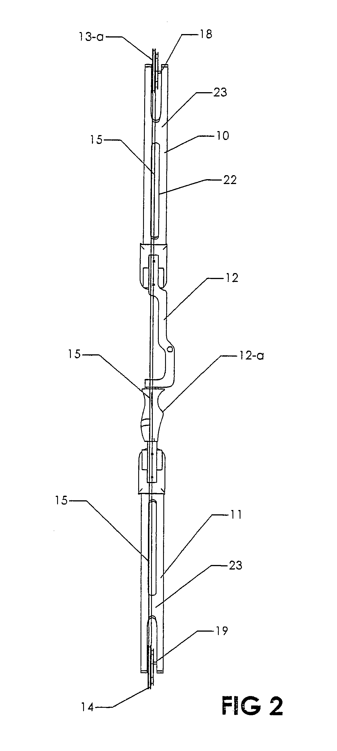
[0028]Referring more particularly to the accompanying drawings, and in the first instance to FIG. 1 thereof, the bow assembly comprises generally upper and lower resilient limbs generally designated 10 and 11 joined in the manner to be disclosed to a rigid riser, generally designated 12, which can be fashioned of aluminum or other suitable material. Revolvable mechanical advantage creating pulley members 13 and 14 are mounted laterally centrally at the outer ends of the limbs 10 and 11. The members 13 and 14 may comprise regular idler pulleys or eccentric pulleys and in FIG. 1 a regular pulley is shown at 13 and an eccentric pulley at 14. They operate in the usual manner to mount the bow string 15 shown in FIG. 1, which in the embodiment shown is part of the conventional tension cable system generally designated TC which extends between the opposite ends of the bow in the usual manner. The cables TC-1 and TC-2 of the conventional cable system, pass through spaced apart openings in a...


PUM


Abstract

A compound archery bow with a handle-providing rigid riser and flexible limbs on the riser mounting bow string pulleys has damping interconnection mechanism between the limbs and riser. A damper is carried by each riser inboard of a riser limb seat. A resilient limb cup for each limb seat has portions for engaging the bottom, side walls and inner end wall of a limb and a fastener extends from each limb through each limb cup and limb seat to secure the limb to the damper. Pulley members with bow string tracks are journaled on the outer ends of the flexible limbs. The pulley members relate about lateral axes of revolution. A vertically extending bow string is trained around the revolvable pulley members. The bow string tracks lie in the same front to rear vertical plane. At least of the pulley members comprises an eccentric cam.

Description

RELATED APPLICATIONS[0001]This invention is entitled to the priority of U.S. provisional application Ser. No. 60 / 261,851 filed Jan. 15, 2001, and is a division of Ser. No. 10 / 047,644, filed Jan. 15, 2002, now U.S. Pat. No. 6,718,963, and is a division of Ser. No. 10 / 822,889 filed Apr. 13, 2004 now U.S. Pat. No. 6,941,937. The invention relates to archery bows and more particularly to compound archery bows utilizing separable limb and riser components.BACKGROUND OF THE INVENTION[0002]One of the problems with achieving accuracy has been the recoil vibration occurring as the arrow is released from the bow, which has resulted also in undue noise that startles the game. Another factor affecting accuracy is the alignment of the bow string which in the past has not provided the balance desired. To the best of my knowledge, the arrow released by prior art compound bows has not been vertically centered with the result that the torque and flex stresses on the bow upper and lower limbs has not...

Claims


Application Information

Patent Timeline
IPC IPC(8): F41B5/00
CPCF41B5/10F41B5/1426F41B5/105
Inventor WHEELER, MARK G.
Owner WHEELER MARK G
Why Eureka
Try Eureka