Vehicle control apparatus

a technology for controlling apparatus and vehicles, applied in the direction of steering initiation, vessel construction, instruments, etc., can solve the problems of uncomfortable or stressed occupants sitting in front passenger seats, and achieve the effect of preventing unnecessary steering control

Inactive Publication Date: 2013-08-29
DENSO CORP +1
View PDF5 Cites 55 Cited by
  • Summary
  • Abstract
  • Description
  • Claims
  • Application Information

AI Technical Summary

Benefits of technology

[0017]This allows the offset to be adjusted properly depending on situations outside the lane, such as positions of off-lane obstacles relative to the vehicle, varying with time.
[0018]Preferably, in the apparatus, a status indication unit indicates to occupants of the vehicle at least one of an offset adjustment result of the offset adjustment unit and a vehicle path estimation of the vehicle-path estimation unit. This allows the occupant to be aware that the offset has been changed due to the presence of the designated occupant or a change

Problems solved by technology

With this configuration, however, since the intended lateral position of the vehicle is offset away from the protruding objects (regarded as obstacles) regardless of the presence of an occupant sitting in a front passenger seat or the like, a vehicle traveling in a lan

Method used


Image

  • Vehicle control apparatus
  • Vehicle control apparatus
  • Vehicle control apparatus

Examples


first embodiment

(Overall Configuration)

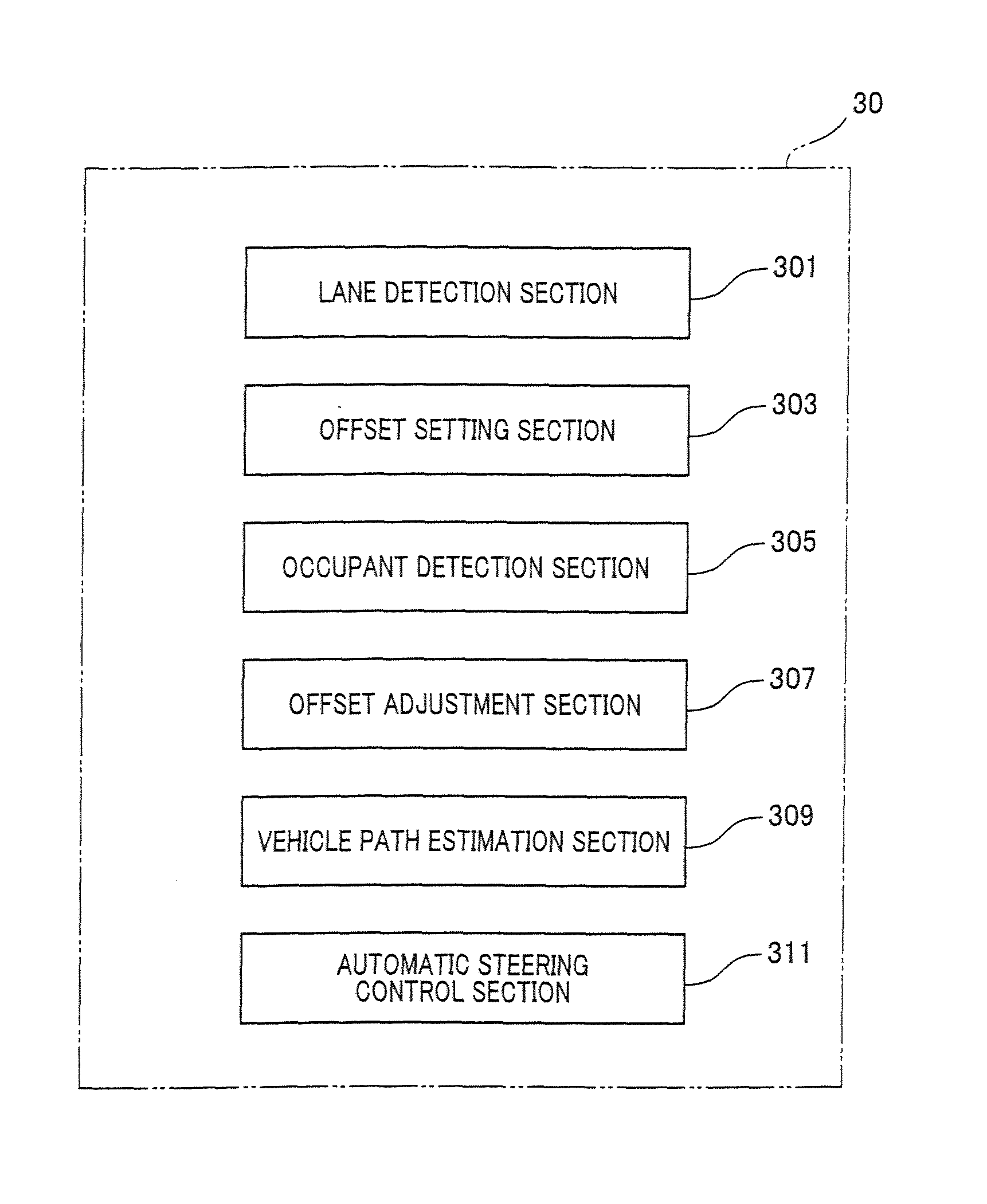
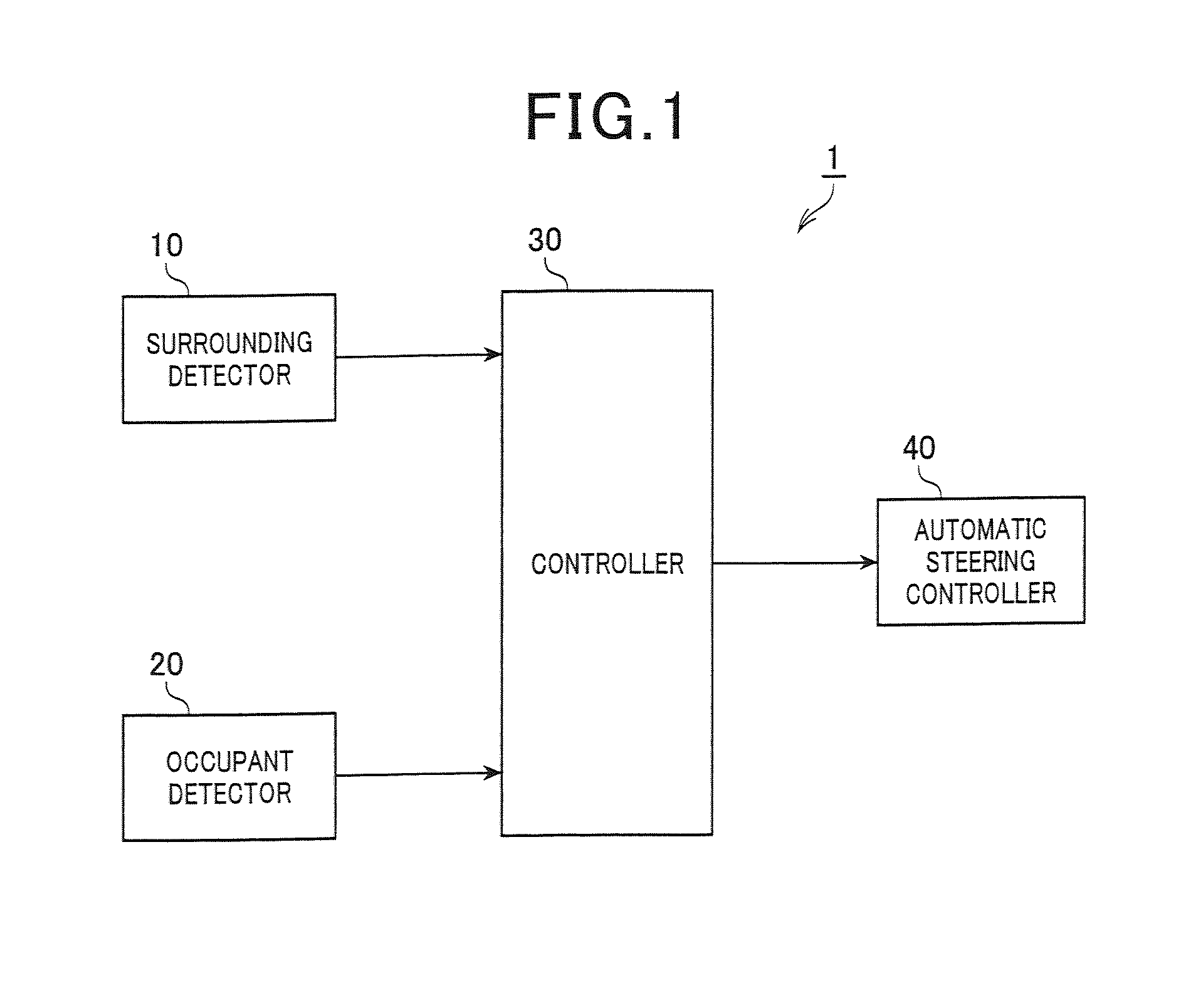
[0042]A vehicle control apparatus 1 in accordance with a first embodiment of the present embodiment, as shown in FIG. 1, includes a surrounding detector 10 that detects surroundings around the own vehicle (i.e., the vehicle mounting the apparatus therein), an occupant detector 20 that detects the presence of occupants other than a driver, a controller 30 that estimates a desired vehicle path on the basis of detection results of the surrounding detector 10 and the occupant detector 20 and generates a steering instruction for driving the own vehicle along the estimated vehicle path, and an automatic steering controller 40 that automatically controls steering in response to the steering instruction from the controller 30.

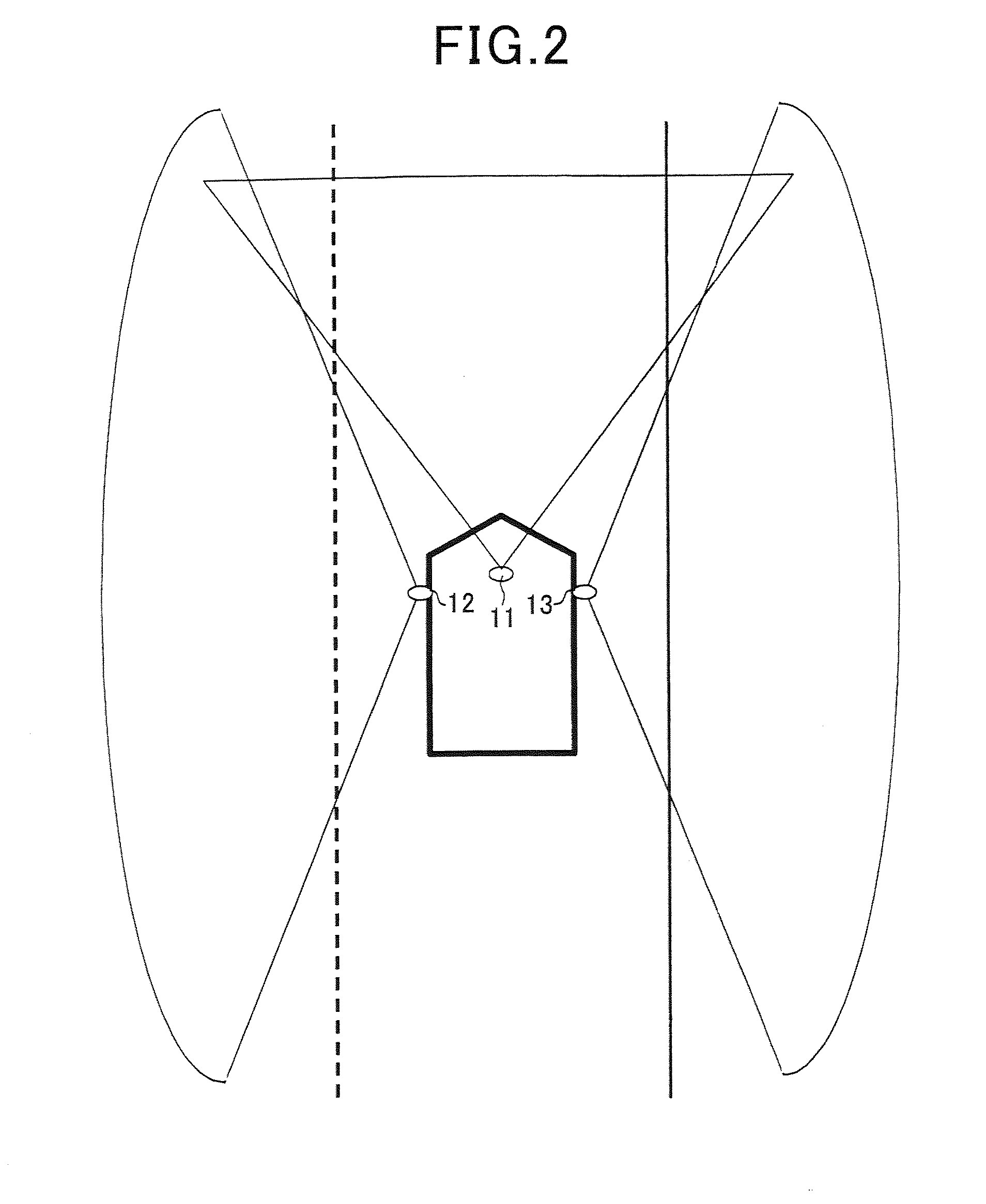
[0043]As shown in FIG. 2, the surrounding detector 10 includes at least a forward sensor 11 that detects surroundings in a forward area, encompassing a first predetermined angle range, centered on the direction of travel of the own vehicle, a lef...

second embodiment

[0067]There will now be explained a second embodiment of the present invention. Only differences of the second embodiment from the first embodiment will be explained.

[0068]As shown in FIG. 6A, the controller 30 of the second embodiment is similar to the controller 30 of the first embodiment shown in FIG. 3A except that an obstacle detection section 313 is added to the controller 30 of the first embodiment.

(Lane Keeping Control)

[0069]As shown in FIG. 6B, steps S112, S114 are added and step S122 replaces step S120 as compared to the lane keeping control process of the first embodiment shown in FIG. 3B.

[0070]In step S112 subsequent to step S110, surroundings outside the target lane (hereinafter referred to as off-lane surroundings) are detected on the basis of the detection results of the left and right side sensors 12, 13.

[0071]More specifically, off-lane obstacles, such as lane partition protuberances, vehicles traveling side by side with the own vehicle, parked vehicles, terrains an...

third embodiment

[0079]There will now be explained a third embodiment of the present invention.

(Overall Configuration)

[0080]A vehicle control apparatus 2 in accordance with a third embodiment of the present embodiment, as shown in FIG. 8, includes an occupant state detector 50 comprised of an image sensor that captures images of the vicinity of a face of each occupant, in addition to the surrounding detector 10, the occupant detector 20, the controller 30, and the automatic steering controller 40.

[0081]Only differences of the third embodiment from the first embodiment will be explained. As shown in FIG. 9A, the controller 30 of the third embodiment is similar to the controller 30 of the first embodiment shown in FIG. 3A except that an occupant state detection section 315, an inhibition section 317, and an eye level estimation section 319 are added to the controller 30 of the first embodiment.

(Offset Adjustment Process)

[0082]As shown in FIG. 9B, in the offset adjustment process of the present embodim...


PUM


Abstract

A vehicle control apparatus capable of automatic steering control while reducing discomfort or stress on vehicle occupants. In the apparatus, a lane detection unit detects a lane in which the vehicle is traveling. An offset setting unit sets an offset within the lane suitable for making a driver feel less stressed. An occupant detection unit detects the presence of a designated occupant of a seat opposite a driver's seat. An offset adjustment unit, when the designated occupant is detected, adjusts the offset set by the offset setting unit to be decreased. A vehicle-path estimation unit estimates a vehicle path in the lane such that the vehicle can travel along the vehicle path from a current lateral position to a target lateral position of the vehicle. An automatic steering control unit automatically controls steering so that the vehicle travels along the estimated vehicle.

Description

CROSS-REFERENCE TO RELATED APPLICATION[0001]This application is based on and claims the benefit of priority from earlier Japanese Patent Application No. 2012-41823 filed Feb. 28, 2012, the description of which is incorporated herein by reference. cl BACKGROUND[0002]1. Technical Field[0003]The present invention relates to a vehicle control apparatus for automatic steering control.[0004]2. Related Art[0005]A known vehicle control apparatus capable of automatic steering control, as disclosed in Japanese Patent Application Laid-Open Publication No. 2007-22134, detects white lines from a captured image forward of or behind a vehicle mounting the apparatus therein (also referred to as the own vehicle) and performs the automatic steering control such that the vehicle keeps traveling near the middle of a lane bordered by the detected white lines. When a white line having a sequence of protruding objects thereon serving as a lane separator is detected, the steering is controlled so that the ...

Claims


Application Information

Patent Timeline
IPC IPC(8): B62D6/00G05D1/02
CPCB62D1/28G05D1/021B62D6/001B62D15/0265
Inventor UEDA, YUSUKETOMINAGA, MOTONORITSURUTA, TOMOHIKOHATOH, TAKESHI
Owner DENSO CORP
Why Eureka
Try Eureka