
Plastic-acceptor hybrid components

a technology of plastic acceptors and hybrid components, applied in the field of plastic acceptor hybrid components, can solve the problems of poor heat resistance, liquid adhesives that require bulky and expensive spraying equipment, and each adhesive employed to date comes with its own unique set of problems, so as to achieve less internal stresses and high bond strength

Inactive Publication Date: 2008-03-20
NOKIA CORP
View PDF4 Cites 57 Cited by
  • Summary
  • Abstract
  • Description
  • Claims
  • Application Information

AI Technical Summary

Benefits of technology

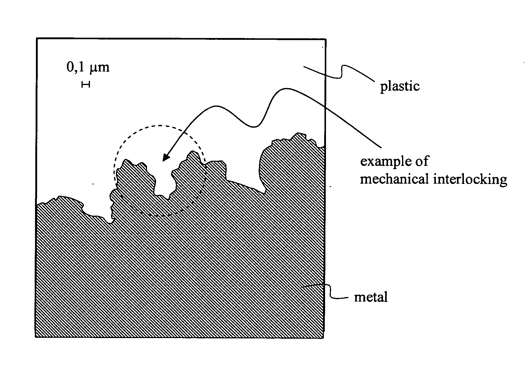
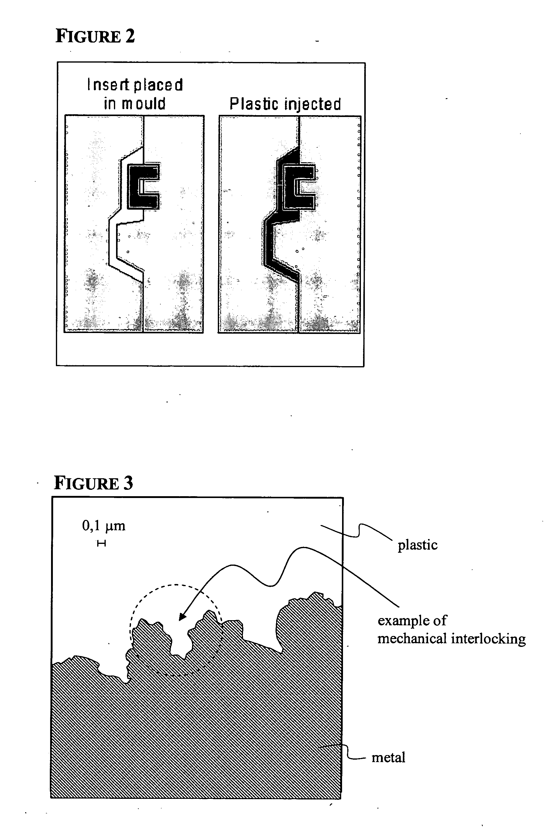
[0008]The present inventors have surprisingly found that by allowing a molten plastic to permeate into the surface structure, i.e. cavities, of a previously roughened acceptor component and clamping together, a hybrid component of substantially each kind of solid material with any plastic material may be obtained. By injection compression moulding of plastic onto an acceptor insert, a stable and durable plastic-acceptor hybrid component is obtained solely by anchoring of the cooled and hardened acceptor component in the roughened surface structure of the acceptor component. The present invention provides further an apparatus suitable to obtain the present hybrid component and for performing the present method.
[0009]An advantage is hereby that the roughened acceptor component does not require any other treatment in order to “accept” or “receive ” the molten plastic component in the roughened surface and to form a join between the two materials. Another advantage is that the plastic feature on the acceptor component surface is not visible to the other side of a hybrid part which is the case in conventional insert injection moulding that relays on mechanical locking of plastic through the acceptor component. A further advantage resides in that there is no limitation with regard to the used plastic and / or acceptor component, in that each kind of plastic material, which may be subjected to injection compression moulding, may be used. Still another advantage resides in high bond strengths between the plastic and acceptor component leading in case of tension applied often in breaking of the plastic component and not in breaking at the bond line, i.e. the metal-plastic interface. Injection compression moulding further produces less internal stresses into a hybrid part compared to a part that has been manufactured by using conventional insert moulding. The present method permits well defined constructions of different acceptor and plastic components for grounding or electrostatic discharge (ESD) issues.

Problems solved by technology

Unfortunately, every adhesive employed to date comes with its own unique set of problems.
For example, thermoplastic powders, films, webs and hot melts must be applied in accordance with very restrictive time and temperature parameters and yield poor heat resistance.
In addition, liquid adhesives require the use of bulky and expensive spraying equipment, and related cleaning and overspray disposal systems, for effective application.
Such adhesives, however, may exhibit a premature bond failure.
After several years the bond formed by the adhesive fails.
This causes the covering to peel and results in an unsightly product that must either be patched or replaced.
There exist, however, several inherent disadvantages to the above mentioned methods for the production of hybrid components.
Gluing may offer difficulties in mass-production, particularly in maintaining a constant quality.
Mechanical methods suffer from design limitations, in that e.g. mechanical locking requires plastic for both side of the insert increasing thickness of device.

Method used


Image

  • Plastic-acceptor hybrid components
  • Plastic-acceptor hybrid components
  • Plastic-acceptor hybrid components

Examples


example 1

[0050]In a first step a preformed steel part has been roughened by sand blasting to form micro-scale holes in an average depth of from 30 to 100 μm and width of from 15 to 30 μm. The surface structure has been checked by taking SEM-pictures (data not shown).

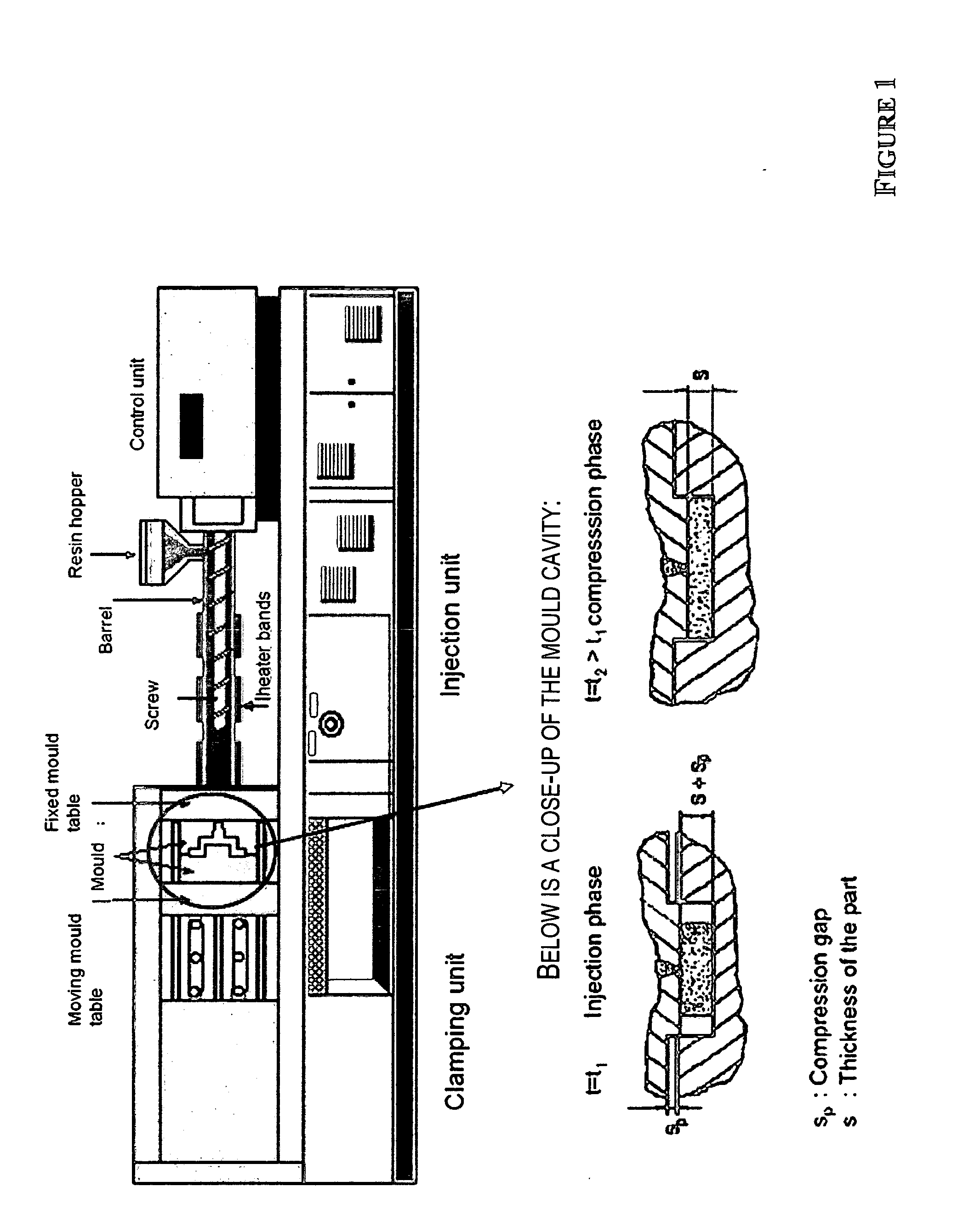
[0051]The preformed steel part has been inserted in an ICM tool as schematically depicted in FIG. 1 and a PBT melt has injected to the roughened surface after that compression / clamping phase has been started within a few seconds.

[0052]The cooled steel-PBT hybrid component has been subjected to a tension force by fixing the metal part and applying a slowly increasing mechanical pressure on the plastic part, wherein the direction of the applied force is substantially parallel to the surface of the metal part. In several tests it could be shown that PBT breaks at substantially the point at which the pressure has been applied, i.e. that the steel-PBT interface has the same or higher strength towards mechanical stresses than the PBT m...

example 2

[0053]According to the above mentioned example a steel-PPS hybrid component has been produced. Said hybrid component shows in case of application of breakage stress the same behaviour as steel-PBT hybrid component, indicating that the metal-plastic interface is more resistant towards stresses than the plastic part itself.

example 3 and 4

[0054]A preformed glass part of window grade has been roughened by sand blasting to form micro-scale holes in an average depth of from 30 to 100 μm and width of from 15 to 30 μm.

[0055]According to the previous examples PBT melt and PPS melt have been applied for the formation of PBT-glass and PPS-glass hybrid components. Also said hybrid components have been subjected to tension forces directed one time to the plastic part and the other time to the glass part. In both cases, plastic and glass parts have failed before breaking of the respective plastic-glass interfaces.


PUM

PropertyMeasurementUnit
Pressureaaaaaaaaaa
Depthaaaaaaaaaa
Forceaaaaaaaaaa

Abstract

The present invention relates generally to plastic-acceptor hybrid components and, more particularly, to the direct bonding of over-moulded plastics to an acceptor insert, such as a metal, in an injection moulding tool. A method and apparatus are provided allowing the production of the present plastic-acceptor hybrid components in which the bonding of said components is obtained by anchoring the plastic component in micro-holes formed in the surface of an acceptor component.

Description

FIELD OF THE INVENTION[0001]The present invention relates generally to plastic-acceptor hybrid components, and more particularly to the direct bonding of over-moulded plastics to an acceptor insert, such as a metal, in an injection moulding tool. A method and apparatus are provided allowing the production of the present plastic-acceptor hybrid components in which the bonding of said components is obtained by anchoring the plastic component in micro-holes formed in the surface of an acceptor component.BACKGROUND[0002]Hybrid components are components, which are formed of different materials, such as metal and plastic. In several technical fields the application of such hybrid components is desirable, such as the production of housings for devices. Composite materials are also often used in vehicle construction, e.g. for reinforcing supporting elements. Hybrid components are particularly at their respective contact points, i.e. the area in which the two materials are connected, subject...

Claims


Application Information

Patent Timeline
IPC IPC(8): G11B5/64
CPCB29C45/1418B29C45/14311Y10T428/24355B29C2045/14237B29C2045/14868B29C45/561
Inventor LASAROV, HARRIKILPI, PEKKA
Owner NOKIA CORP
Learn More