Mixing bowl with attachment

a technology of attachment and mixing bowl, which is applied in the direction of mixing, rotary stirring mixer, transportation and packaging, etc., can solve the problems of complicated sticking problems and inconvenient use, and achieve the effect of improving mixing effect and reducing sticking difficulty

Active Publication Date: 2008-01-01
NEW METRO DESIGN LLC
View PDF25 Cites 62 Cited by
  • Summary
  • Abstract
  • Description
  • Claims
  • Application Information

AI Technical Summary

Problems solved by technology

This inconvenience can be particularly common for thicker batters like cheesecake, creaming together butter and sugar or even muffin and cookie dough.
In addition to sticking on the sides of the bowl, food tends to build up in the dimpled area at the very bottom of the bowl, which further complicates the sticking problem.

Method used


Image

  • Mixing bowl with attachment
  • Mixing bowl with attachment
  • Mixing bowl with attachment

Examples


Embodiment Construction

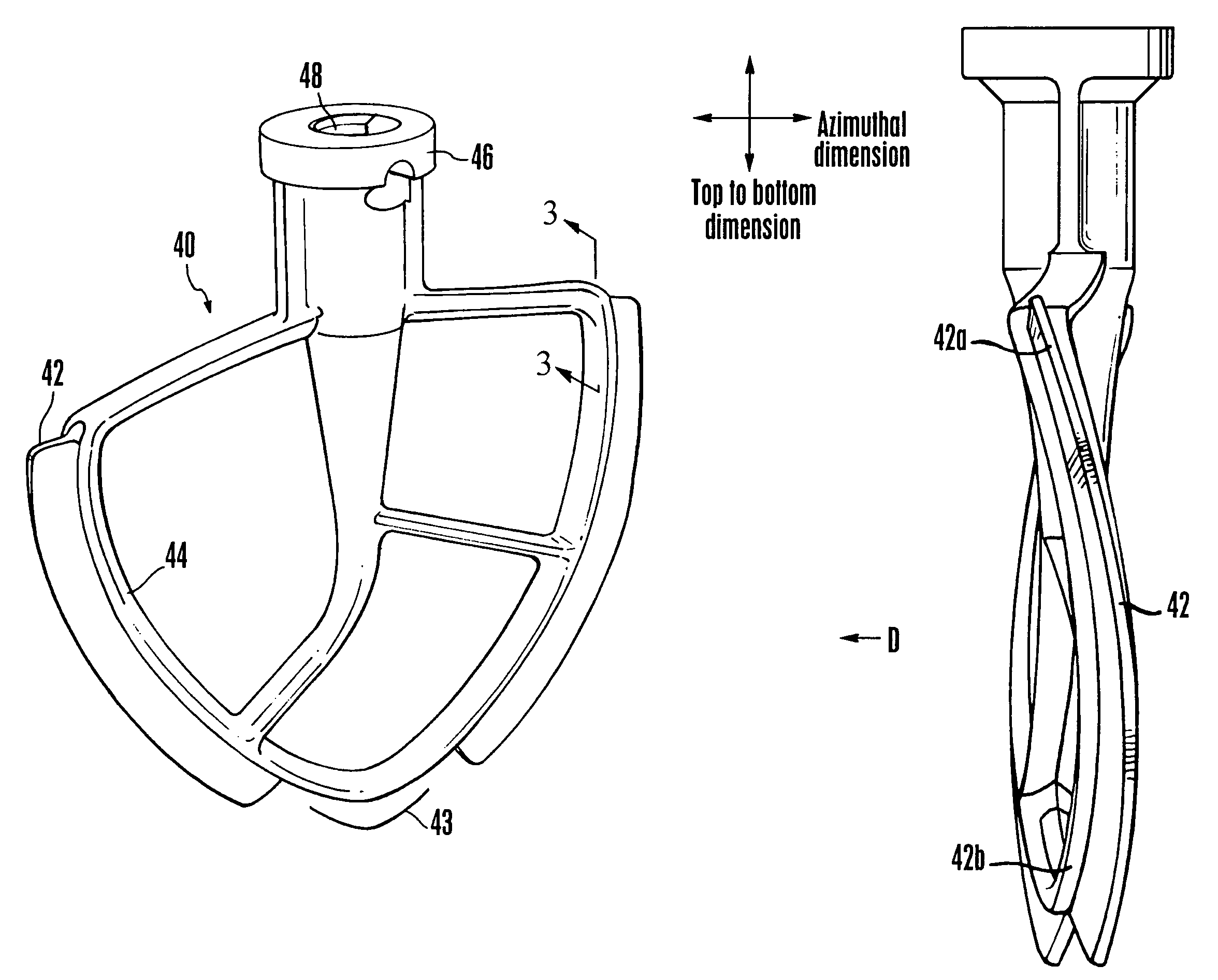
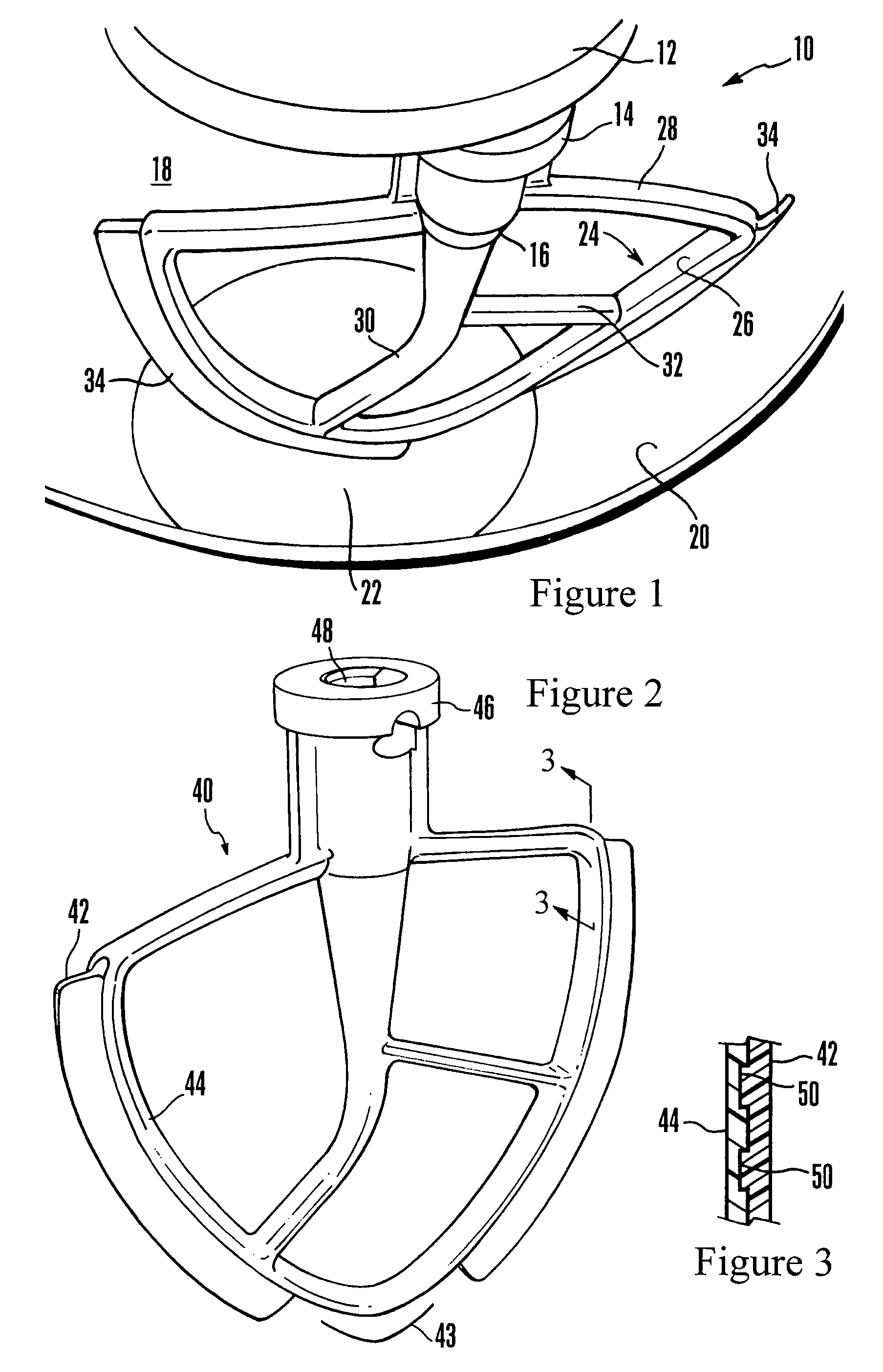
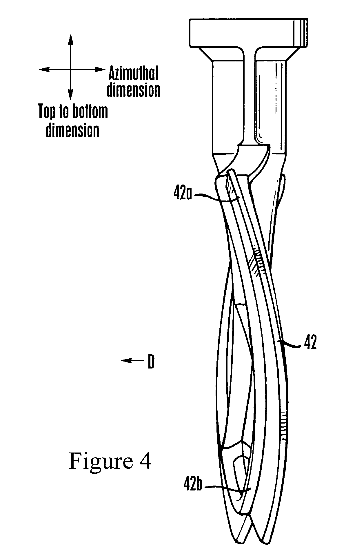
[0015]Referring initially to FIG. 1, a mixer generally designated 10 includes a turning component 12, such as, e.g., a planetary-type turning element, with which an upper engagement member 14 of a mixing attachment 16 can be releasably engaged in accordance with mixing attachment engagement principles known in the art. The mixer 10 can be activated to move the attachment 16 for mixing food in a bowl 18 that has a side 20 and a bottom 22. In some embodiments the side 20 of the bowl may be substantially cylindrical near the open top of the bowl as shown, and can assume a parabolic-like shape or other curved and / or tapering shape as it tapers down toward the bottom 22 of the bowl 18. In any case, the attachment 16 may be a unitarily-made piece of injection molded plastic that is relatively rigid when formed, such as, e.g., Delrin™ or polycarbonate. Or, it may be metal.

[0016]As shown in FIG. 1, the mixing attachment 16 may have two and only two arms 24 that depend down from the upper en...


PUM


Abstract

A food mixing attachment includes two mixing arms extending down from an engagement member that is configured for engaging a mixer. A respective flexible blade is on each arm and has a contour generally like that of a bowl. During the mixing process the blades scrape food from the bowl surface into the interior of the bowl.

Description

FIELD OF THE INVENTION[0001]The present invention relates generally to mixing bowl attachments.BACKGROUND OF THE INVENTION[0002]Food mixers are present in most kitchens. Many food mixers include a revolving planetary element that has a rotating beater shaft with which an attachment such as a wire whisk or mixing beater can be attached, with the attachment revolving with the planetary element as well as rotating with the shaft. As the planetary element revolves and the attachment rotates, the attachment moves through food constituents in a bowl placed under the planetary element to mix, beat, or otherwise process the food constituents.[0003]As recognized by the present invention, beaters are a type of attachment that can be used to mix food. During the mixing process, the present invention critically recognizes that it is common for some of the food to stick to the side of the bowl and remain there. This requires that the cook stop the food mixer and scrape food from the side of the ...

Claims


Application Information

Patent Timeline
Patent Type & Authority Patents(United States)
IPC IPC(8): B01F9/12B01F9/16B01F29/83B01F29/85
CPCA47J43/0711B01F27/052B01F27/091B01F27/13B01F27/805B01F2101/1805
Inventor FALLOWES, GARYTAN, WILLIAMGOETZ, DAVID ROBERT
Owner NEW METRO DESIGN LLC
Why Eureka
Try Eureka