

Method and apparatus for detecting a plasma
a plasma and detection method technology, applied in the field of detecting plasmas, can solve the problems of complete system failure, scrapping of products, and degradation of plasma processing performance, and achieve the effect of reliable and process independen
- Summary
- Abstract
- Description
- Claims
- Application Information
AI Technical Summary
Benefits of technology
Problems solved by technology
Method used
Image

Examples
Embodiment Construction
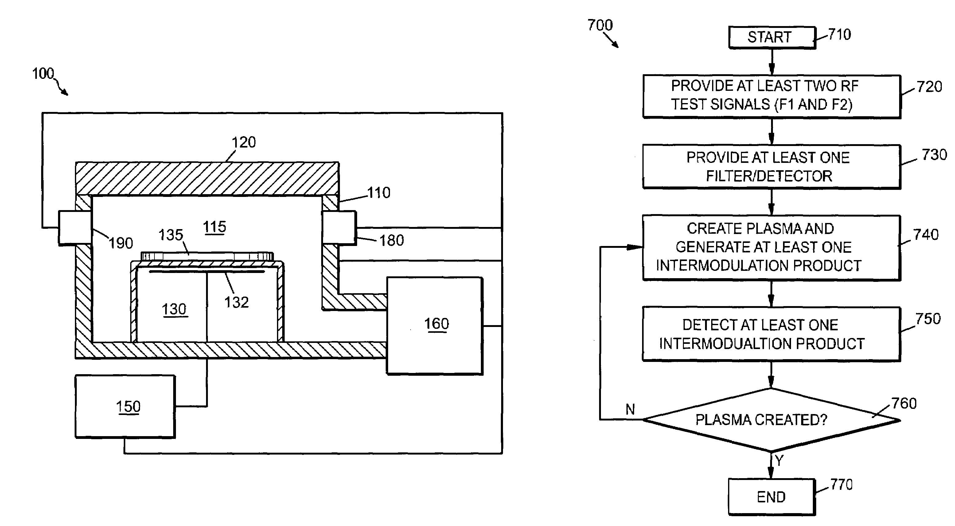
[0022]The present invention is described in the context of a number of exemplary embodiments in which two signals are coupled into a processing space, and the presence or absence of certain intermodulation products of the two signals are detected from the processing space to determine whether or not a plasma is present in the processing space.
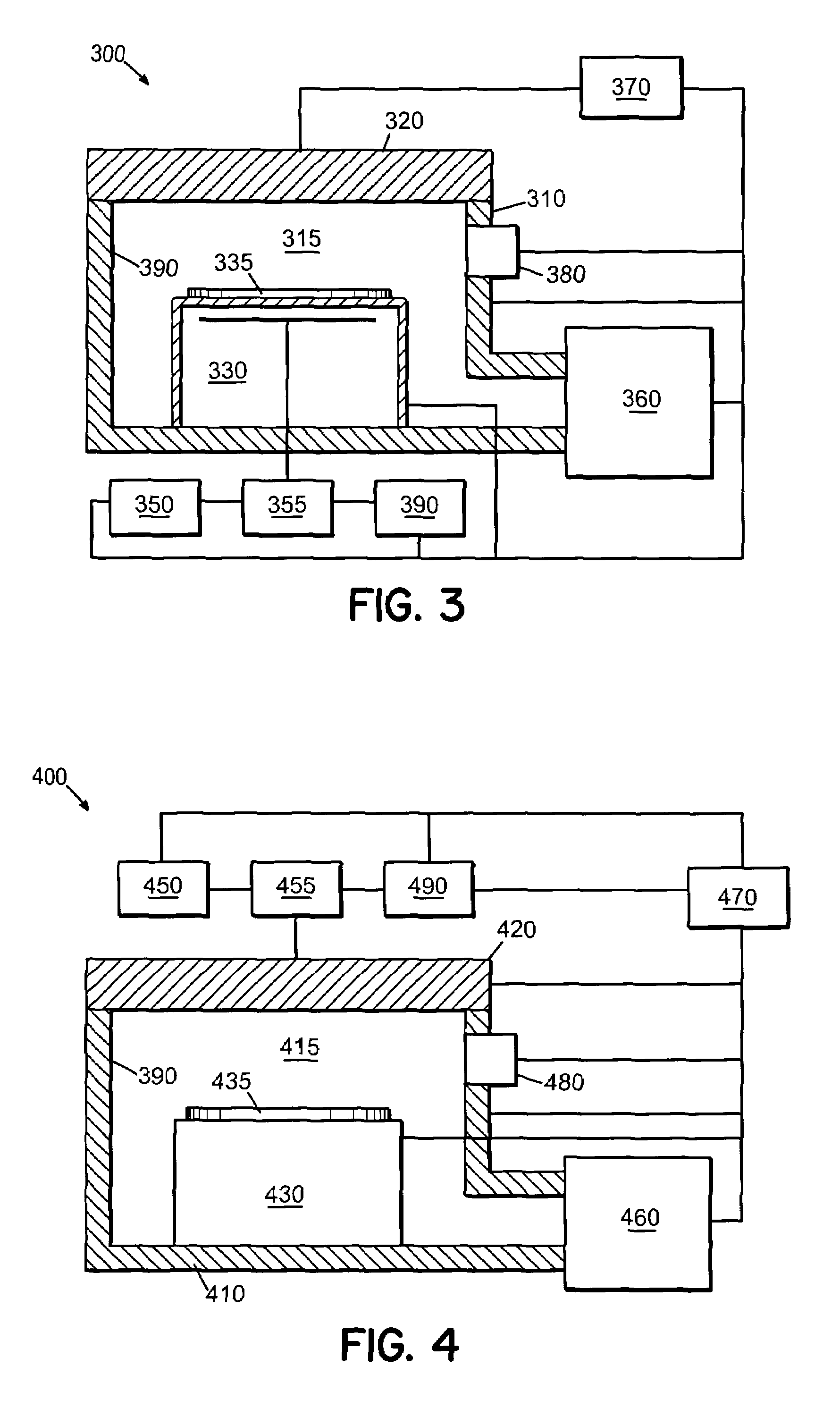
[0023]The present invention provides an improved material processing system that can include a processing tool, which can comprise one or more process chambers. In addition, the processing system can include a plurality of RF-responsive process sensors that are coupled to the processing tool to generate and transmit process data and at least one SIA configured to receive the process data from at least one of the plurality of RF-responsive process sensors.
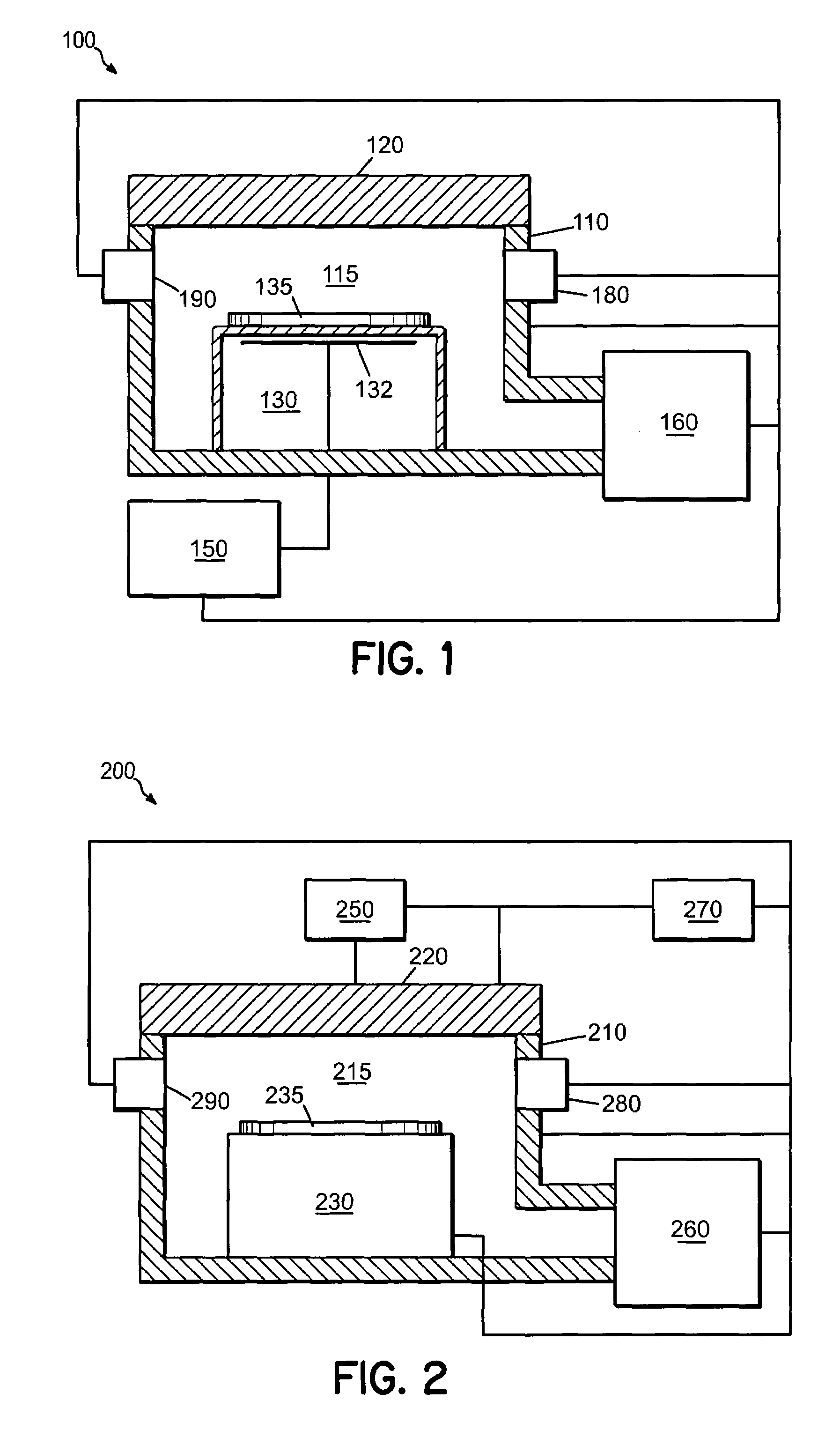
[0024]FIG. 1 illustrates a simplified block diagram for a material processing system in accordance with an embodiment of the present invention. For example, material processing system 100 can c...
PUM
| Property | Measurement | Unit |
|---|---|---|
| frequency | aaaaa | aaaaa |
| frequency | aaaaa | aaaaa |
| frequency | aaaaa | aaaaa |
Abstract
Description
Claims
Application Information