Coiled cable products and methods of forming the same

a technology of coiled cables and products, applied in the field of coiled cables, can solve the problems of difficult handling of cables, difficulty in bending cables, and inability to carry equipment that can exceed the capacity and communication rate of conventional copper wired systems, and achieve the effect of facilitating tangle-free drawing

Inactive Publication Date: 2008-02-12
COMMSCOPE TECH LLC
View PDF2 Cites 20 Cited by
  • Summary
  • Abstract
  • Description
  • Claims
  • Application Information

AI Technical Summary

Benefits of technology

[0010]In other embodiments, the end arranged to be drawn a first end of the cable and the cable has an opposite second end. The looped sections may be selectively arranged to overlap each other rotated about the cross-over section in a first direction to facilitate tangle free drawing of the first end of the cable from the arrangement and rotated about the cross-over section in a substantially opposite second direction to facilitate tangle free drawing of the second end of the cable from the arrangement.
[0011]In further embodiments, cable products are provided including a cable enclosure defining a cable receiving cavity and having a cable receiving opening extending to the cable receiving cavity. A length of springy cable is positioned in the cable receiving cavity and looped in a FIG. 8 arrangement with an intermediate cross-over section between respective first and second looped sections of the cable. The FIG. 8 arrangement enables withdrawal of an end of the cable from the arrangement through the cable receiving opening to linearly extend the length of cable with no more than a single twist of the cable to limit accumulated net linear twist of the cable while linearly extending the cable. The first and second looped sections may be positioned overlapping each other and extending from the cross-over section at an acute angle relative to each other to define a V-shaped region and an end of the cable may extend through the cable receiving opening from the V-shaped region. The acute angle may be selected based on a stiffness of the cable and may be about 10 degrees.
[0015]In yet other embodiments, fiber optic cable products include a cable enclosure defining a cable receiving cavity and having a cable receiving opening extending to the cable receiving cavity. A length of springy fiber optic cable is positioned in the receiving cavity and looped in a FIG. 8 arrangement with an intermediate cross-over section between respective first and second looped sections of the cable. The first and second looped sections are positioned overlapping each other and extending from the cross-over section at an acute angle relative to each other to define a V shaped region. An end of the cable extends through the cable receiving opening from the V shaped region. The FIG. 8 arrangement enables withdrawal of the end of the cable from the arrangement through the cable receiving opening to linearly extend the length of cable with no more than a single twist of the cable to limit accumulated net linear twist of the cable while linearly extending the cable.
[0016]Interior dividing walls are positioned in the cable receiving cavity that separate the first and second looped sections to limit entanglement of the cable when the end is drawn from the cable arrangement. The cable enclosure has a depth selected to provide the acute angle to the overlapping looped sections when the length of cable is positioned in the cable receiving cavity.
[0021]In further embodiments, the second end of the cable is coupled to the enclosure using a retainer and removing the length of cable from the cable receiving cavity includes separating the second end from the enclosure. Placing the rotated looped sections in the cable receiving cavity includes coupling the first end of the cable to the enclosure using a retainer. The cable enclosure may include interior dividing walls positioned in the cable receiving cavity and placing the folded length of cable in the cable receiving cavity may include placing the length of cable in the cable receiving cavity with the interior dividing walls separating the first and second looped sections to limit entanglement of the cable when the end is drawn through the cable receiving opening. Placing the folded length of cable in the cable receiving cavity may further include coupling the looped sections of the cable to the enclosure using removable retainers to maintain the V-shaped region substantially free of cable.
[0023]In further embodiments, methods of coiling a length of springy fiber optic cable include laying the length of cable having a first end and a second end in a FIG. 8 pattern including an intermediate cross-over region between respective first and second looped sections of the cable. The first looped section is folded in a selected direction about the cross-over section into a position overlapping the second looped section with the first and second looped sections extending from the cross-over section at an acute angle relative to each other to define a V-shaped region. The folded length of cable is placed in a cable receiving cavity of a cable enclosure with the cable receiving opening proximate the V-shaped region and with the looped sections positioned in the cable receiving cavity rotated about the cross-over section in the selected direction. The first end of the length of cable extending from the V-shaped region is inserted through the cable receiving opening of the cable enclosure. The selected direction is selected to facilitate tangle free drawing of the first end of the cable from the cable enclosure.

Problems solved by technology

The carrying capacity and communication rate capabilities of such equipment may exceed that provided by conventional copper wired systems.
This may make such cables very difficult to handle.
This twisting can be a problem when a springy cable is being unwound from a conventional reel.
In particular, accumulated twist generally is not good for cables, and fiber cable particularly.

Method used


Image

  • Coiled cable products and methods of forming the same
  • Coiled cable products and methods of forming the same
  • Coiled cable products and methods of forming the same

Examples


Embodiment Construction

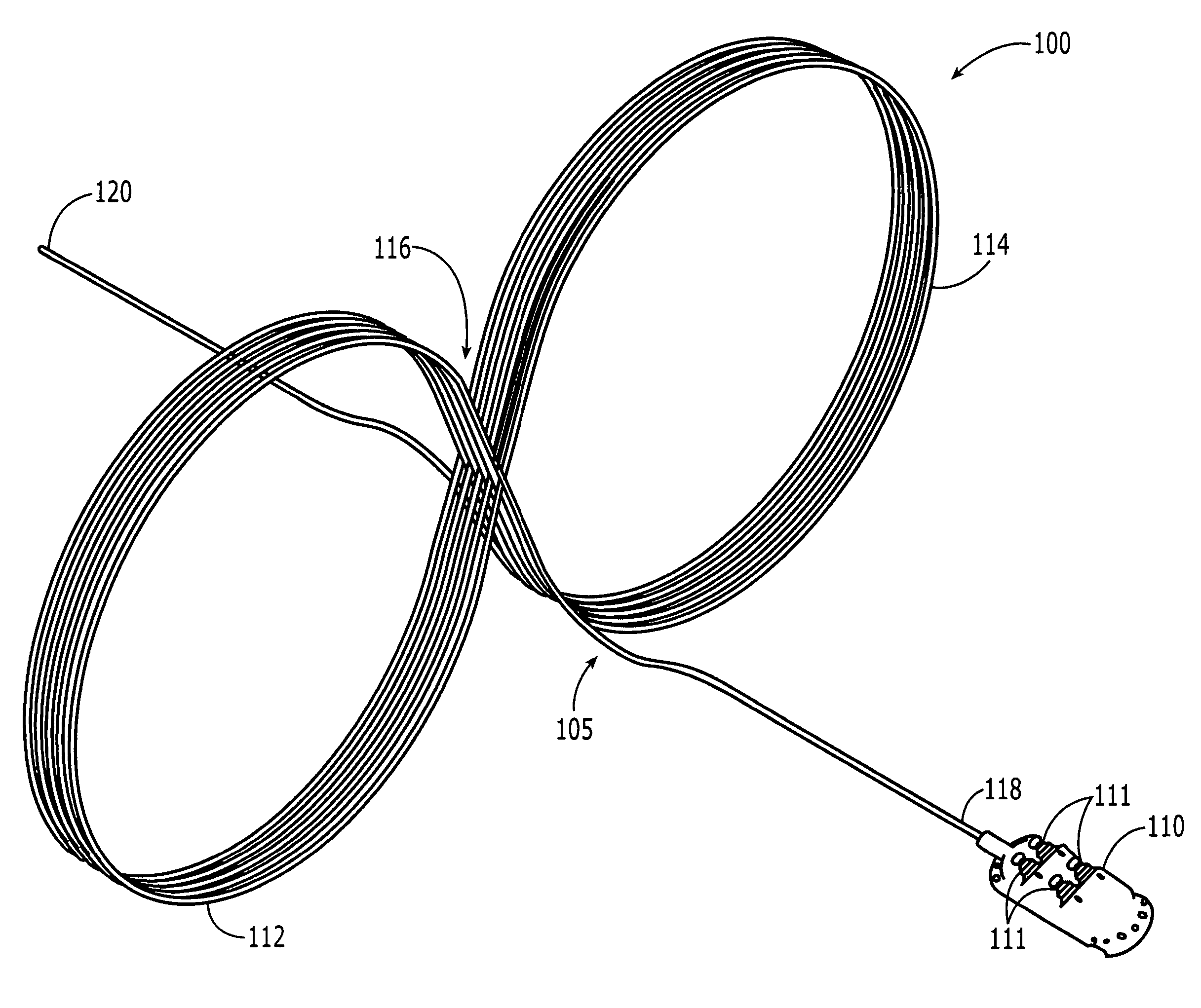
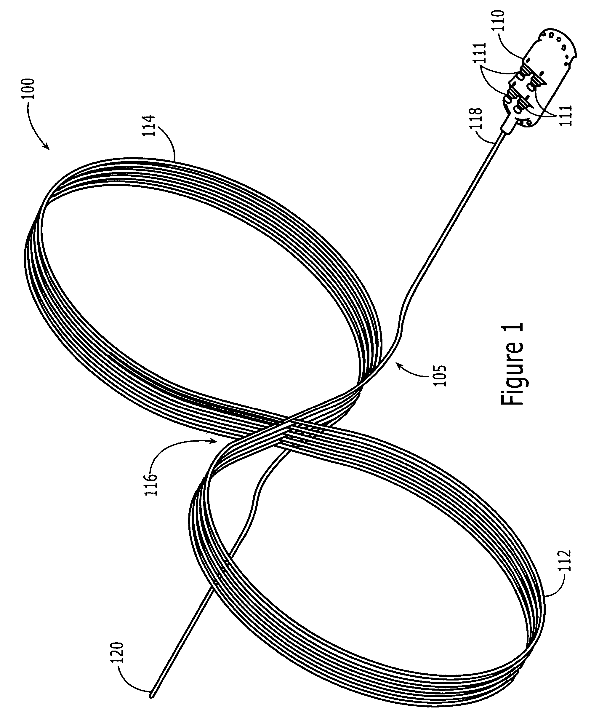
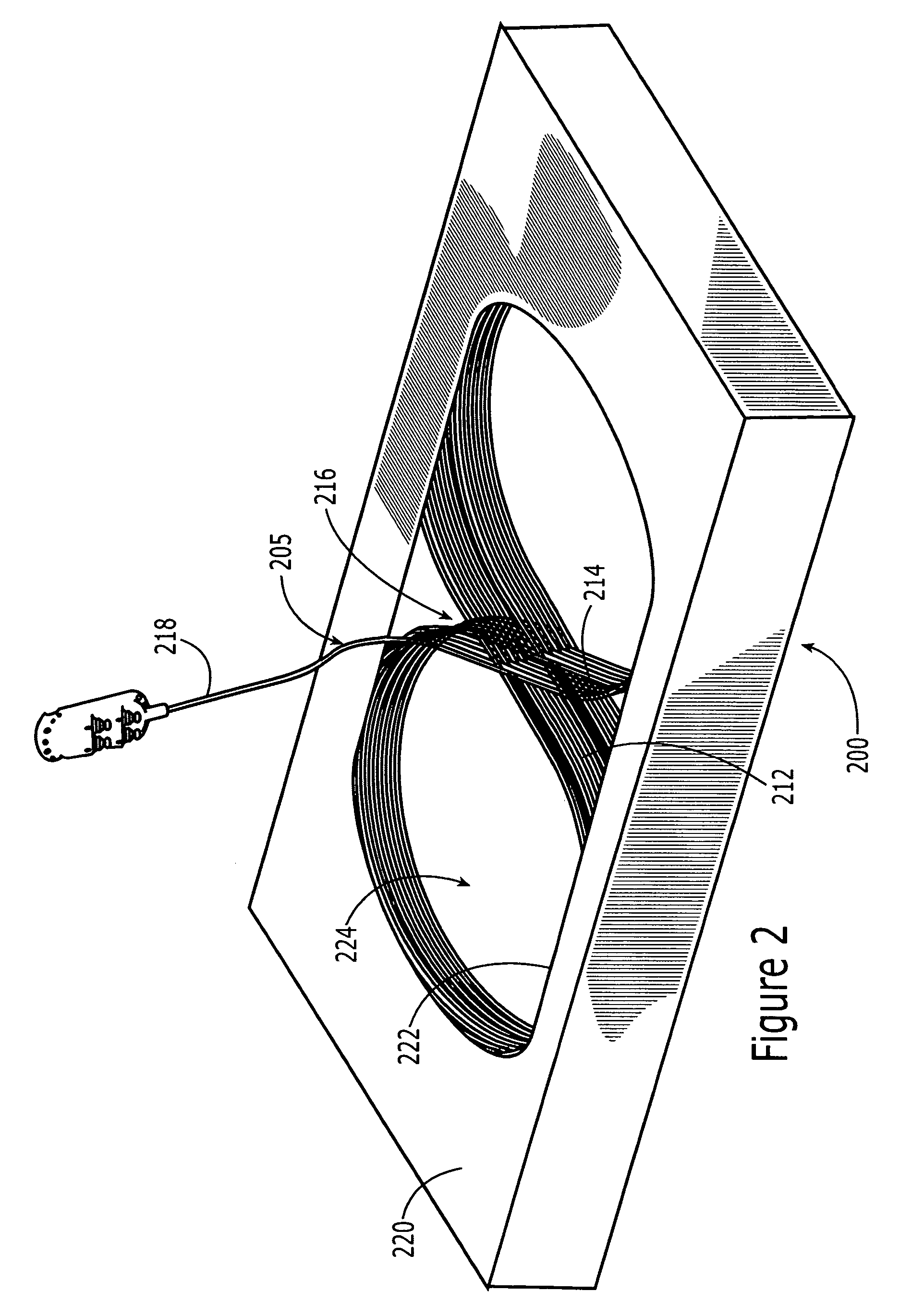
[0035]The present invention now will be described more fully hereinafter with reference to the accompanying drawings, in which illustrative embodiments of the invention are shown. In the drawings, the relative sizes of regions or features may be exaggerated for clarity. This invention may, however, be embodied in many different forms and should not be construed as limited to the embodiments set forth herein; rather, these embodiments are provided so that this disclosure will be thorough and complete, and will fully convey the scope of the invention to those skilled in the art.

[0036]It will be understood that, although the terms first, second, etc. may be used herein to describe various elements, components, regions, layers and / or sections, these elements, components, regions, layers and / or sections should not be limited by these terms. These terms are only used to distinguish one element, component, region, layer or section from another region, layer or section. Thus, a first elemen...


PUM


Abstract

Cable arrangements include a length of springy cable looped in a figure 8 arrangement with an intermediate cross-over section between respective first and second looped sections of the cable. The figure 8 arrangement enables withdrawal of the cable from the arrangement with no more than a single twist of the cable to limit accumulated net linear twist of the cable while linearly extending the cable. The first and second looped sections may be positioned overlapping each other to provide a substantially toroidal shaped cable arrangement. An optical device may be provided on one or both of the ends of the length of cable. The springy cable may be a fiber optic cable, such as flat drop cable. Cable products, enclosures and methods of forming a cable arrangement are also provided.

Description

RELATED APPLICATIONS[0001]The present application claims priority from U.S. Provisional Application No. 60 / 790,407, filed Apr. 7, 2006, the disclosure of which is hereby incorporated herein in its entirety by reference.BACKGROUND OF THE INVENTION[0002]The present invention relates to cable products and, more particularly, to coiled cable products and methods for forming the same.[0003]An extensive infrastructure supporting telecommunication has been developed, traditionally based upon copper wire connections between individual subscribers and telecommunications company network distribution points. More recently, much of the telecommunications network infrastructure is being extended or replaced with an optical fiber based communications network infrastructure. The carrying capacity and communication rate capabilities of such equipment may exceed that provided by conventional copper wired systems.[0004]As such, fiber optic cables are widely used for telecommunications applications wh...

Claims


Application Information

Patent Timeline
Patent Type & Authority Patents(United States)
IPC IPC(8): G02B6/00
CPCG02B6/4439G02B6/4457H01R13/72
Inventor MULLANEY, JULIANROACH, ROBERT A.NGUYEN, ROBERTTHOMPSON, ROY KELLERALSTON, ERIC
Owner COMMSCOPE TECH LLC
Why Eureka
Try Eureka