Implant having a shaft and a hold element connected therewith for connecting with a rod

a technology of holding elements and shafts, applied in the field of implants, can solve problems such as loosening of inner screws, side flanks of receiver members, and affecting the retention for

Active Publication Date: 2008-02-26
BIEDERMANN TECH GMBH & CO KG
View PDF31 Cites 152 Cited by
  • Summary
  • Abstract
  • Description
  • Claims
  • Application Information

AI Technical Summary

Benefits of technology

[0012]the distance (A) between the bottom of the U-shaped recess to the support surface (12; 37) is smaller than the diameter (D) of the rod;
[0013]the distance (A) is smaller than the diameter (D) by an amount of approximately 1% to 7.5% of the diameter (D);

Problems solved by technology

If the thread of the receiver member and of an inner screw is a metric thread, force components in radial direction of the cylindrical receiver member occur when screwing in the inner screw, which could cause splaying of the legs of the receiver member resulting in a loosening of the inner screw.
Such implants that have thin side flanks of the receiver member, however, encounter a problem when using only an inner screw for fixation without an additional securing via a nut to be screwed on or a cap covering the legs of the receiver member at the outside or a ring or the like.
To avoid this, the inner screw should be tightened with reduced torque which, however, impairs the retention force.
Further, the problem also can be reduced, if a wall of the receiver member is very thickly dimensioned, which is, however, an obstacle to the requirement of a compact implant design.

Method used


Image

  • Implant having a shaft and a hold element connected therewith for connecting with a rod
  • Implant having a shaft and a hold element connected therewith for connecting with a rod
  • Implant having a shaft and a hold element connected therewith for connecting with a rod

Examples


Embodiment Construction

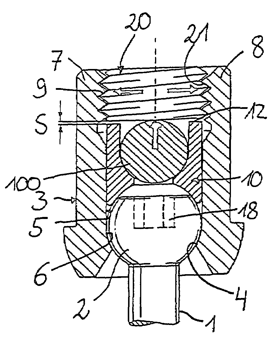
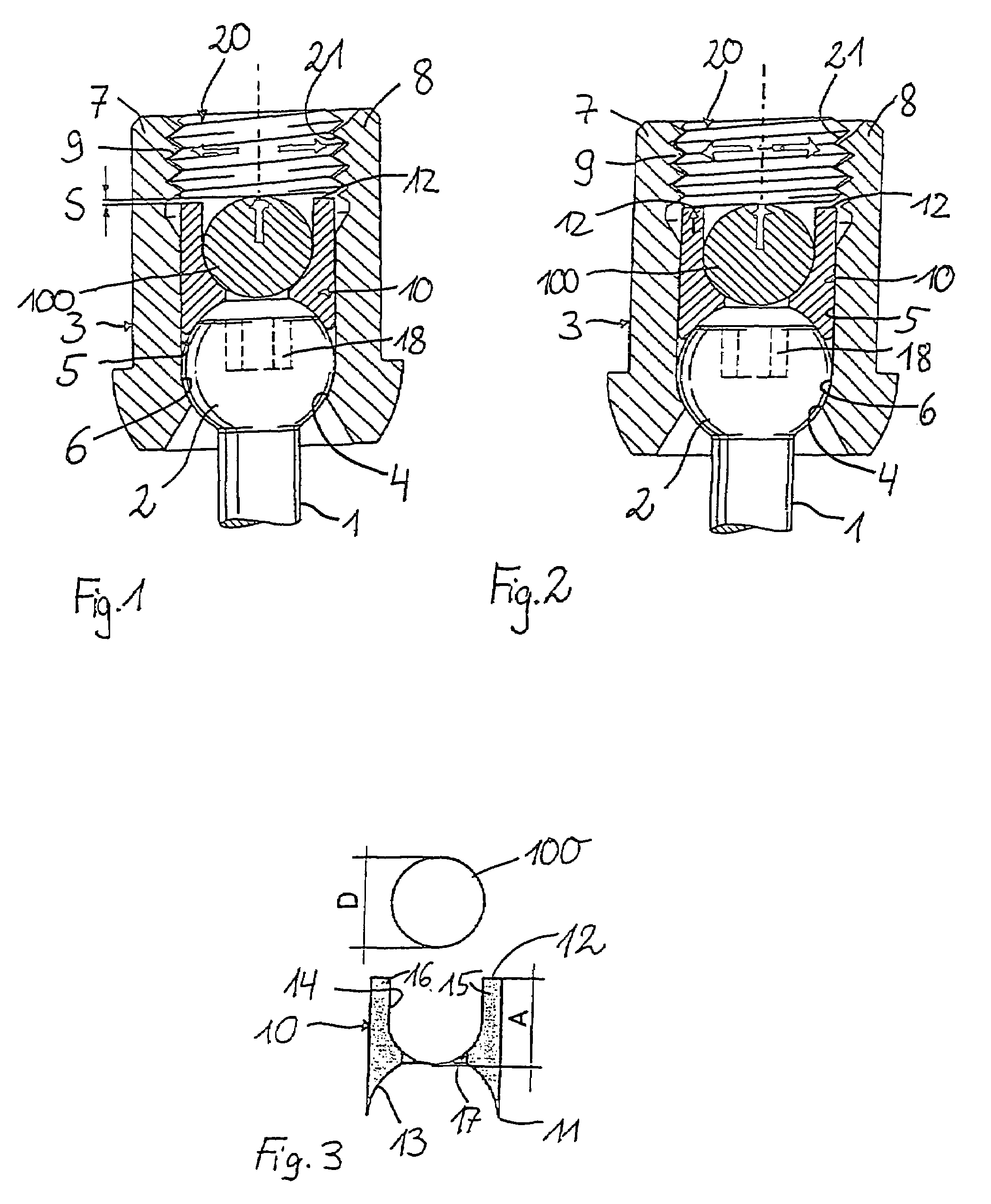
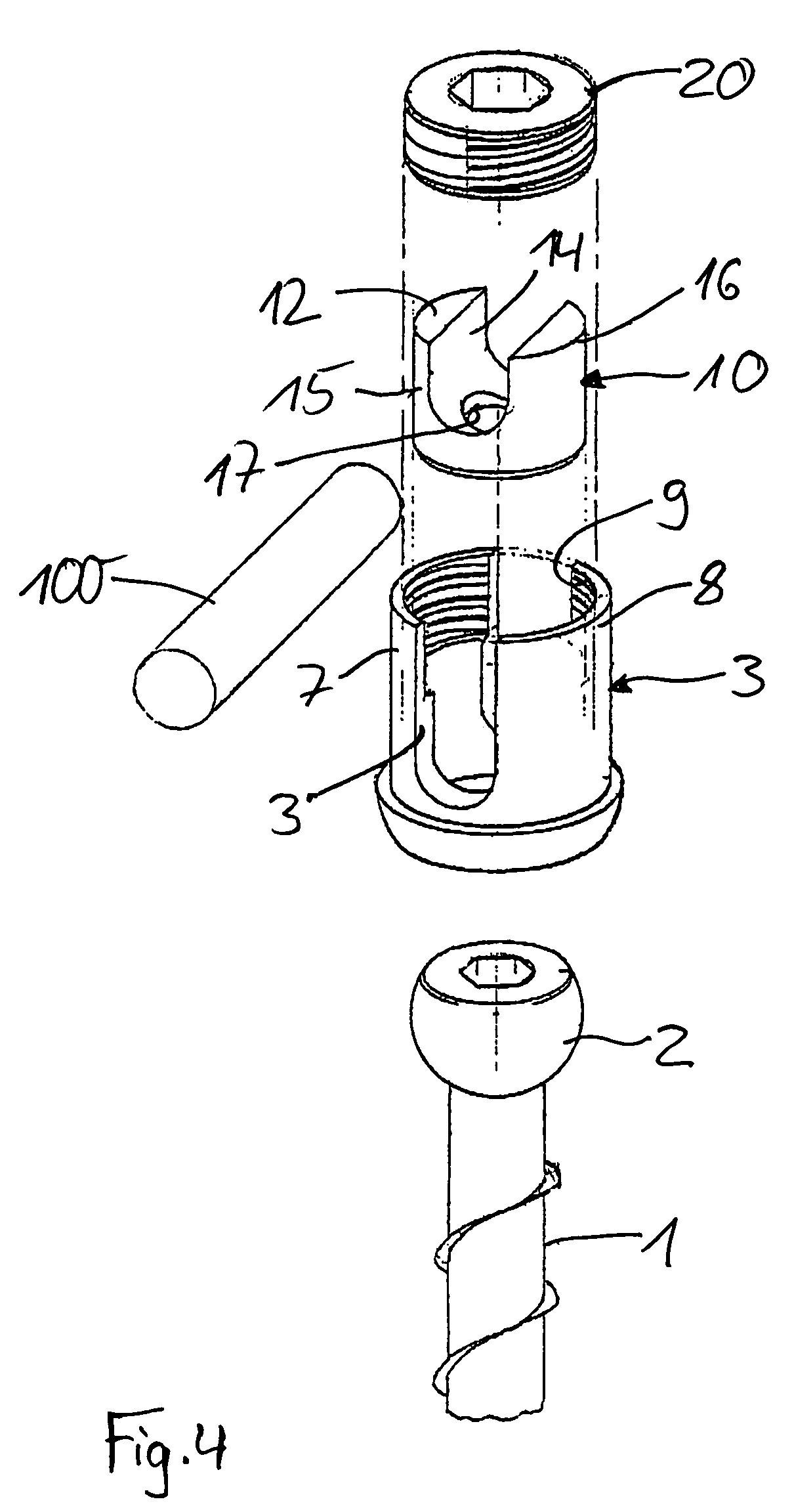
[0031]In the embodiment shown in FIGS. 1 to 4 an implant according to the present invention is formed as a polyaxial screw comprising a screw element having a threaded shaft 1 with a bone thread (not shown) and an integral spherical segment-shaped head 2. The head 2 is held within the receiver member 3. The receiver or holding member 3 has at its one end an axially symmetric first bore 4, the diameter of which is greater than that of the thread section of the shaft 1 and smaller than that of the head 2. Further, the receiver 3 comprises a coaxial second bore 5, which is open at the end opposite to the first bore 4 and the diameter of which is sufficiently large that the screw element can be passed through the open end with its threaded section going through the first bore 4 and with the head 2 held in a section 6 between the bottom of the second bore 5 and the first bore 4. The small coaxial section 6 is provided adjacent to the first bore 4 and is spherically shaped towards the ope...


PUM


Abstract

An implant is described having a shaft and a holding element connected therewith for connecting with a rod. A recess is provided in the holding element that includes a U-shaped cross section for accommodation of the rod and two free legs at one end which include an inner thread. A closure element fixes the rod inserted into the U-shaped recess. The closure element has an outer thread cooperating with the inner thread of the legs. An abutment at or in the holding element limits tilting of the closure element about the rod at the time of final tightening of the closure element in the holding element.

Description

FIELD OF THE INVENTION[0001]The invention relates to an implant to be used in spine or trauma surgery, the implant having a shaft and a holding element connected therewith for connecting with a rod, wherein the holding element comprises a recess having a U-shaped cross section for receiving the rod and two free legs at one end which have an inner thread and a closure element for fixation of the rod inserted into the U-shaped recess, the closure element comprising an outer thread cooperating with the inner thread of the legs.BACKGROUND OF THE INVENTION[0002]EP 0 614 649 B1 describes a polyaxial bone screw with a receiver member with a nut to be screwed onto the receiver member for securing a rod.[0003]If the thread of the receiver member and of an inner screw is a metric thread, force components in radial direction of the cylindrical receiver member occur when screwing in the inner screw, which could cause splaying of the legs of the receiver member resulting in a loosening of the in...

Claims


Application Information

Patent Timeline
Patent Type & Authority Patents(United States)
IPC IPC(8): A61B17/70A61B17/60F16C11/06
CPCA61B17/7032A61B17/7037
Inventor MATTHIS, WILFRIEDBIEDERMANN, LUTZHARMS, JURGEN
Owner BIEDERMANN TECH GMBH & CO KG
Why Eureka
Try Eureka