Apparatus for coupling an implement to a working vehicle

a technology for coupling equipment and working vehicles, which is applied in the direction of agricultural machines, adjusting devices, transportation and packaging, etc., can solve the problems that the angle change between the tractor and the implement does not have as much effect on the working depth of the implement, and achieves the effect of reducing the entire cost of production of the coupling apparatus and substantially simplifying the control of the length-adjustable elements

Inactive Publication Date: 2008-04-08
DEERE & CO
View PDF22 Cites 16 Cited by
  • Summary
  • Abstract
  • Description
  • Claims
  • Application Information

AI Technical Summary

Benefits of technology

[0009]Further, as a result of the fact that the tipping axis is located close to the working vehicle i.e. close to the rear axle of the working vehicle, the influence of oscillatory impulses which arise during operation, between the working vehicle and the implement, is reduced or minimized, thereby leading to greatly improved driver comfort. Finally, the configuration has two lower link bars, an upper link bar, and two lifting thrust elements, which is comparable to a customary three-point hitch configuration, but with this configuration the effective articulation points of the two lower link bars, the upper link bar, and the two lifting thrust elements are disposed on the side directed toward the implement rather than on the side directed toward the working vehicle.
[0053]In another embodiment, a rotational movement between the working vehicle and the implement is achievable by coupling of the two length-adjustable lower link bars. The term “coupling” here is intended to mean particularly a crossed interconnection of the cylinder chambers, resulting in opposite piston movement in the two cylinders. With such a coupling of the two length-adjustable lower link bars, one can advantageously realize movement along a very tight curve (turning radius) compared to the known art, in that the amount of shortening of one of the lower link bars is the same as the amount of lengthening of the other lower link bar. The same principle makes it possible to realize a degree of freedom around the longitudinal axis of the tractor, by means of the two lifting elements, and at the same time to advantageously bear the supported loads applied from the implement.

Problems solved by technology

Thus, changes in the angle between the tractor and the implement do not have as much effect on the working depth of the implement.

Method used


Image

  • Apparatus for coupling an implement to a working vehicle
  • Apparatus for coupling an implement to a working vehicle
  • Apparatus for coupling an implement to a working vehicle

Examples


Embodiment Construction

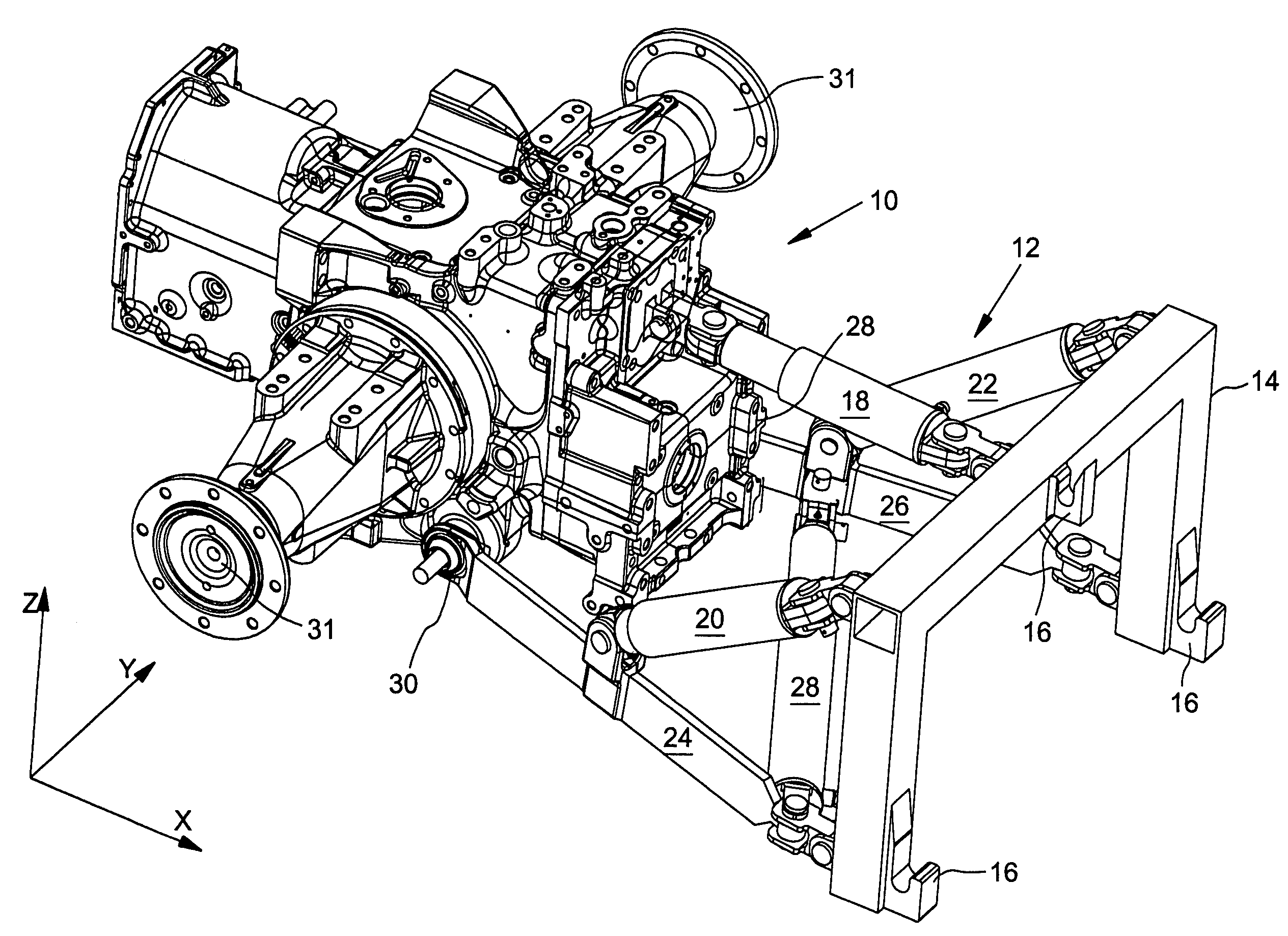
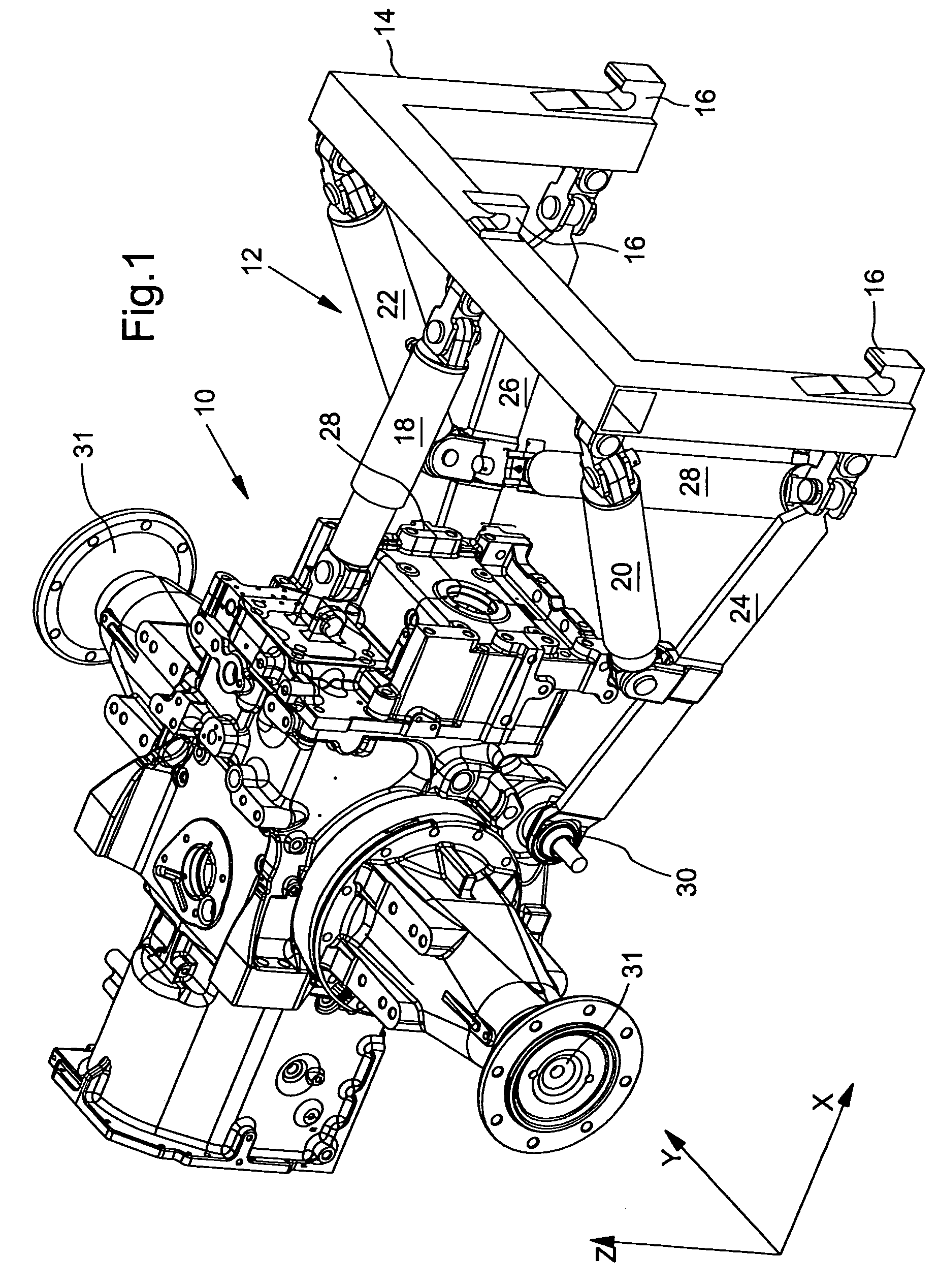
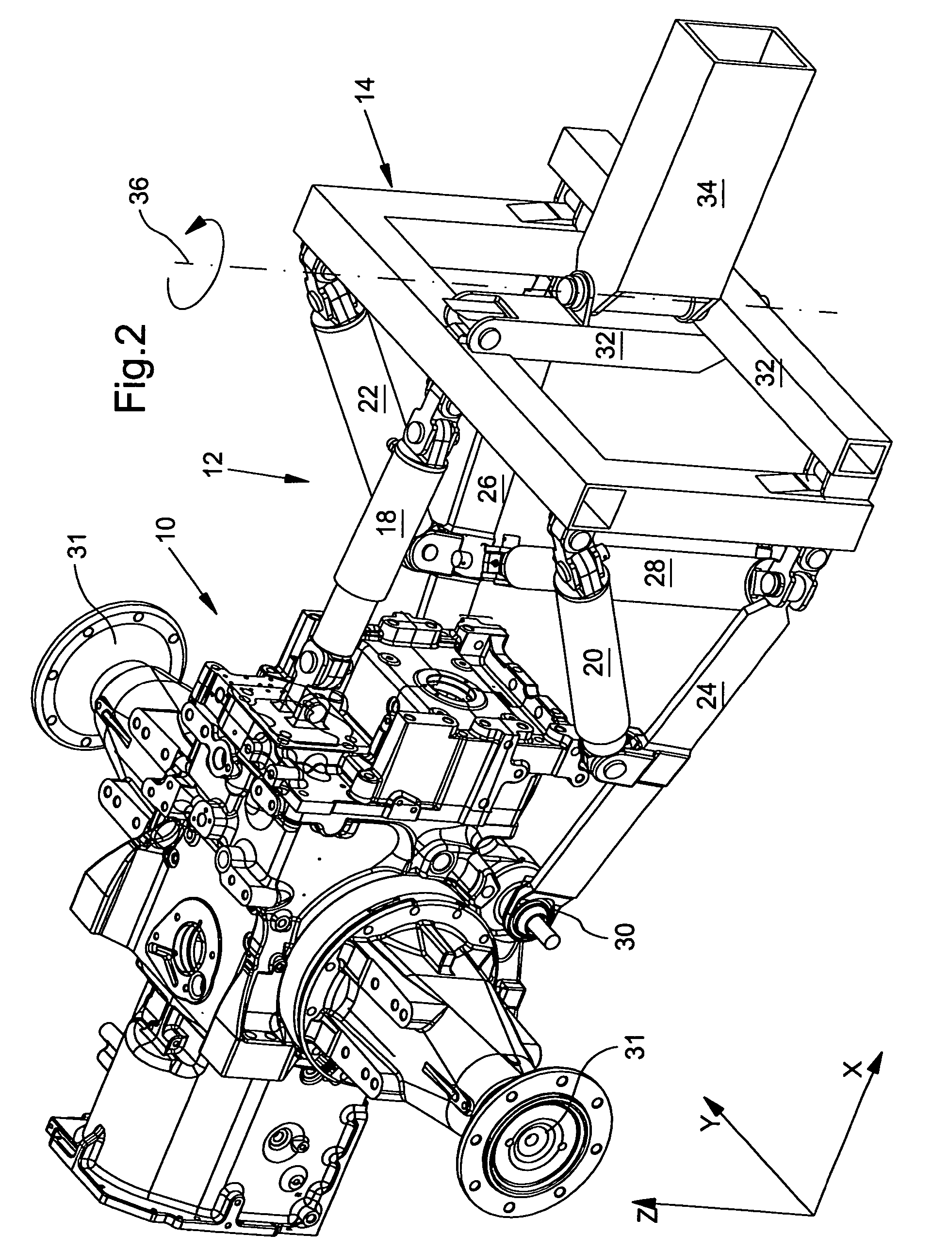
[0066]In the figures, similar or analogous component parts have been labeled with like reference numerals. In FIGS. 1 and 2, an axle housing 10 of a working vehicle (not further illustrated) is shown, to which a coupling apparatus 12 is adapted. The axle housing 10 shown in FIGS. 1 and 2 is a part of a tractor. An implement (also not illustrated in FIG. 1) is adapted to be connected to the tractor via the coupling apparatus 12. The implement is adapted to, inter alia, the coupling frame 14 via coupling means 16 which are in the form of upwardly open hooks. The three-point functionality of a customary three-point hitch is provided by the coupling frame 14 with its coupling means 16. The coupling frame 14 via its configuration with the coupling means 16 serves as an adapting interface for an implement.

[0067]The coupling apparatus 12 comprises a length-adjustable upper link bar 18, two lifting elements 20, 22, and two lower link bars 24, 26. The upper link bar 18 enables, inter alia, t...


PUM


Abstract

The present invention relates to an apparatus for coupling an implement to a working vehicle, having two lower link bars, a length-adjustable upper link bar, and two lifting elements. The end closest to the working vehicle, of each of the lower link bars and the upper link bar, is swingably mountable, and the other end closest to the implement is likewise swingably mountable. The upper link bar is essentially disposed centrally in the upper region of the coupling apparatus. The two lower link bars are disposed essentially laterally in the lower region of the coupling apparatus. One end of each of the lifting elements can be swingably mounted on a respective lower link bar. A supported load from the implement which acts on the working vehicle does not lead to diminishment of the load on a vehicle axle. For this purpose, the coupling apparatus is characterized in that the respective other ends of the lifting elements directed toward the implement, can be swingably mounted in essentially an upper region of the coupling apparatus.

Description

FIELD OF THE INVENTION[0001]The present invention relates to an apparatus for coupling an implement to a working vehicle, the apparatus comprising two lower link bars, a length-adjustable upper link bar, and two lifting elements. The one end of each of the lower link bars and the upper link bar closest to the working vehicle, is swingably mountable with respect to the vehicle, and the other end closest to the implement is likewise swingably mountable with respect to the implement. The upper link bar is essentially disposed centrally in the upper region of the coupling apparatus. The two lower link bars are disposed essentially laterally in the lower region of the coupling apparatus. One end of each of the lifting elements can be swingably mounted on a respective lower link bar.BACKGROUND OF THE INVENTION[0002]Devices of this type are commonly used for coupling an implement to an agricultural or industrial tractor, truck or other utility vehicle. The implement may generally be a mach...

Claims


Application Information

Patent Timeline
Patent Type & Authority Patents(United States)
IPC IPC(8): A01B51/00A01B59/06B60D1/14
CPCA01B59/068B60D1/141E02F9/2239E02F9/2242
Inventor NORDHOFF, HENDRIK
Owner DEERE & CO
Why Eureka
Try Eureka