Vacuum cleaner fan unit and access aperture

a vacuum cleaner and fan unit technology, applied in the field of vacuum cleaners, can solve the problems of affecting the service life of the vacuum cleaner,

Active Publication Date: 2008-04-22
TECHTRONIC FLOOR CARE TECH LTD
View PDF7 Cites 112 Cited by
  • Summary
  • Abstract
  • Description
  • Claims
  • Application Information

AI Technical Summary

Problems solved by technology

The fan unit is usually in the interior of the vacuum cleaner mechanism, and is relatively difficult to access.
In the prior art, accessing the fan unit is typically difficult and time-consuming.

Method used


Image

  • Vacuum cleaner fan unit and access aperture
  • Vacuum cleaner fan unit and access aperture
  • Vacuum cleaner fan unit and access aperture

Examples


Embodiment Construction

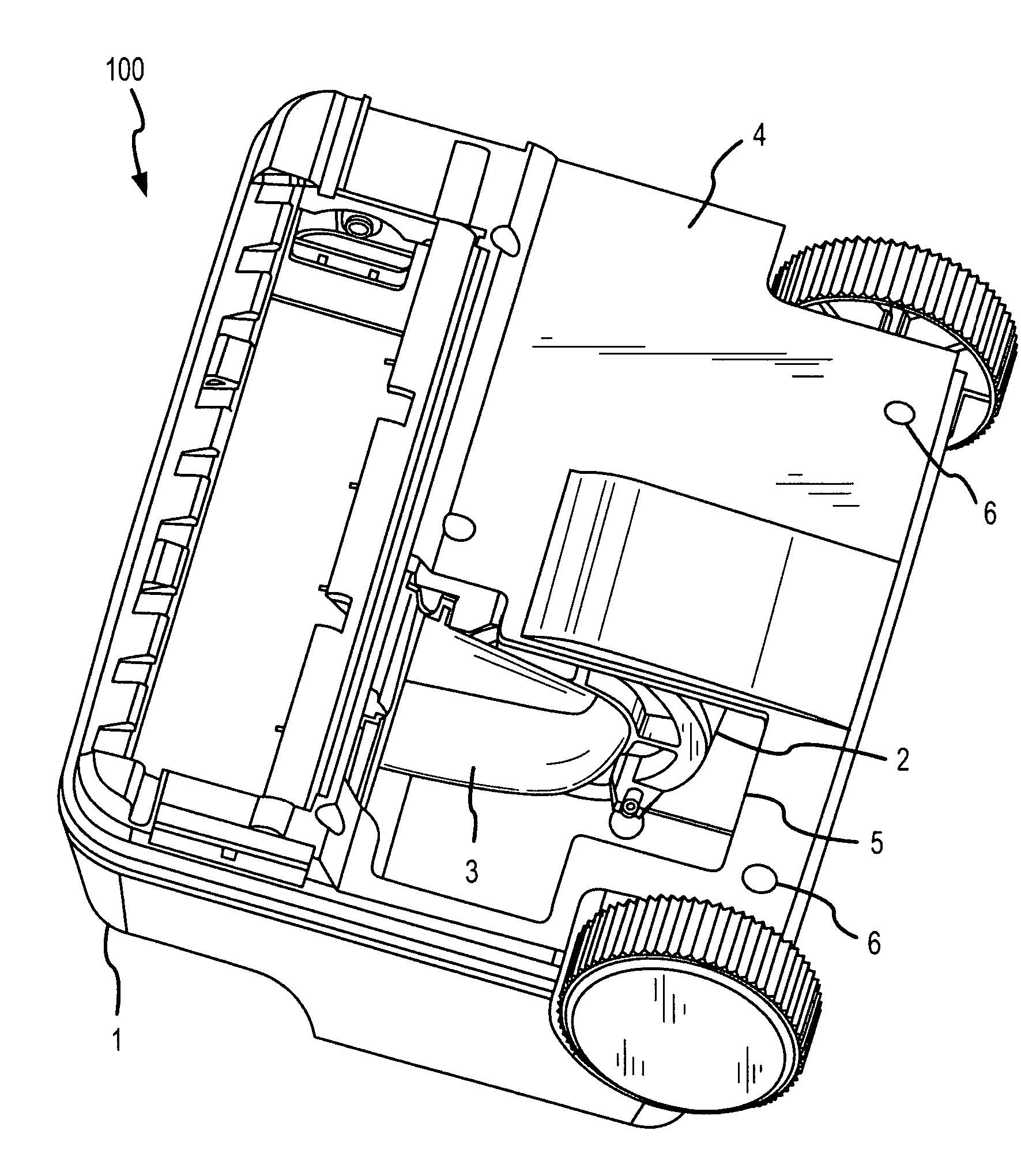
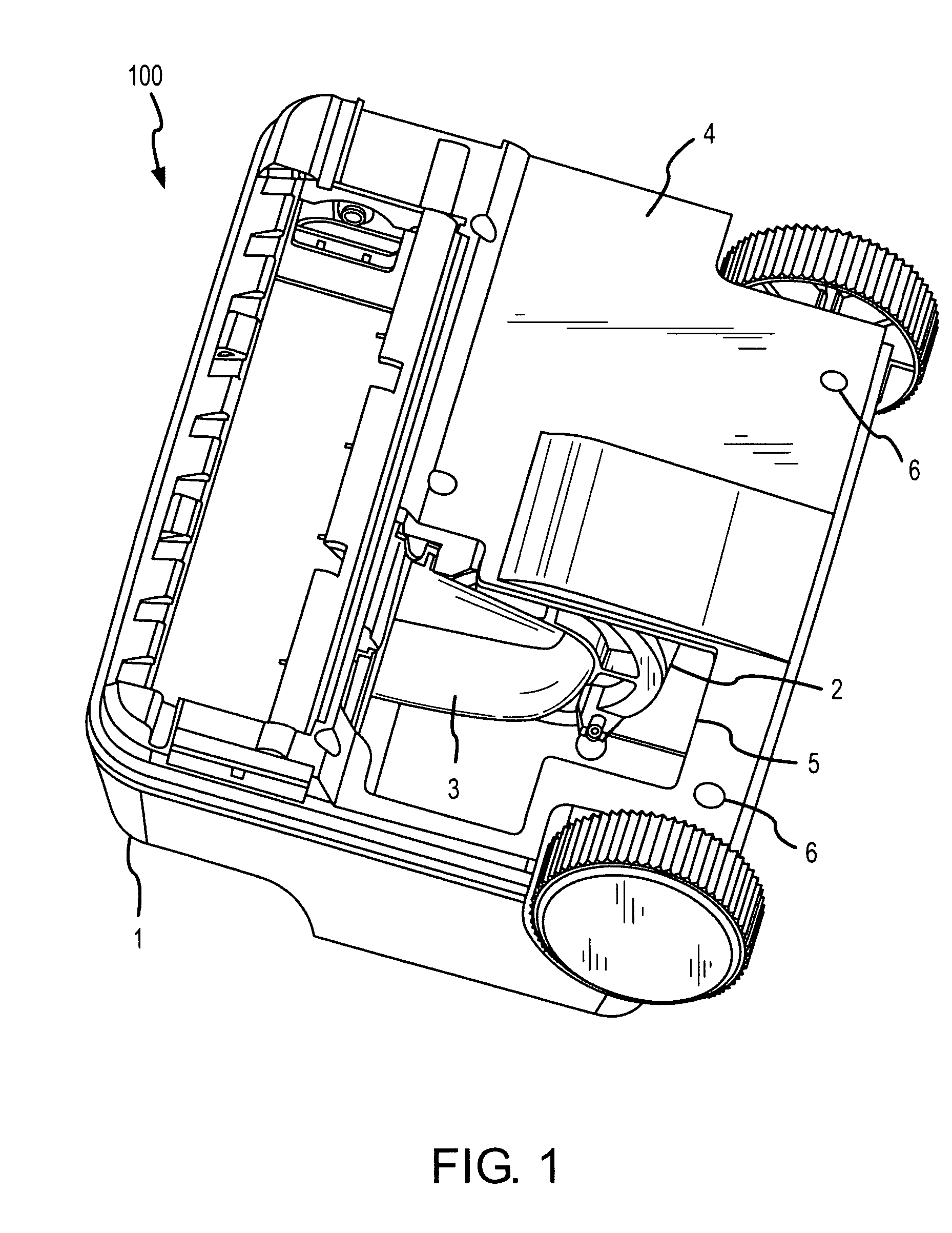
[0026]FIG. 1 is a bottom view of a vacuum cleaner 100 according to an embodiment of the invention. The vacuum cleaner 100 includes a chassis 1, a blower housing 2, an inlet housing 3, and a baseplate 4.

[0027]The vacuum cleaner shown is an upright floor model. However, it should be understood that the vacuum cleaner can be a canister, portable, shop, industrial, or specialized vacuum cleaner.

[0028]The chassis 1 includes an exterior surface and can include frame and support members to provide mounting surfaces for various components of the vacuum cleaner 100. For example, the blower housing 2 and the inlet housing 3 can be mounted to the chassis 1.

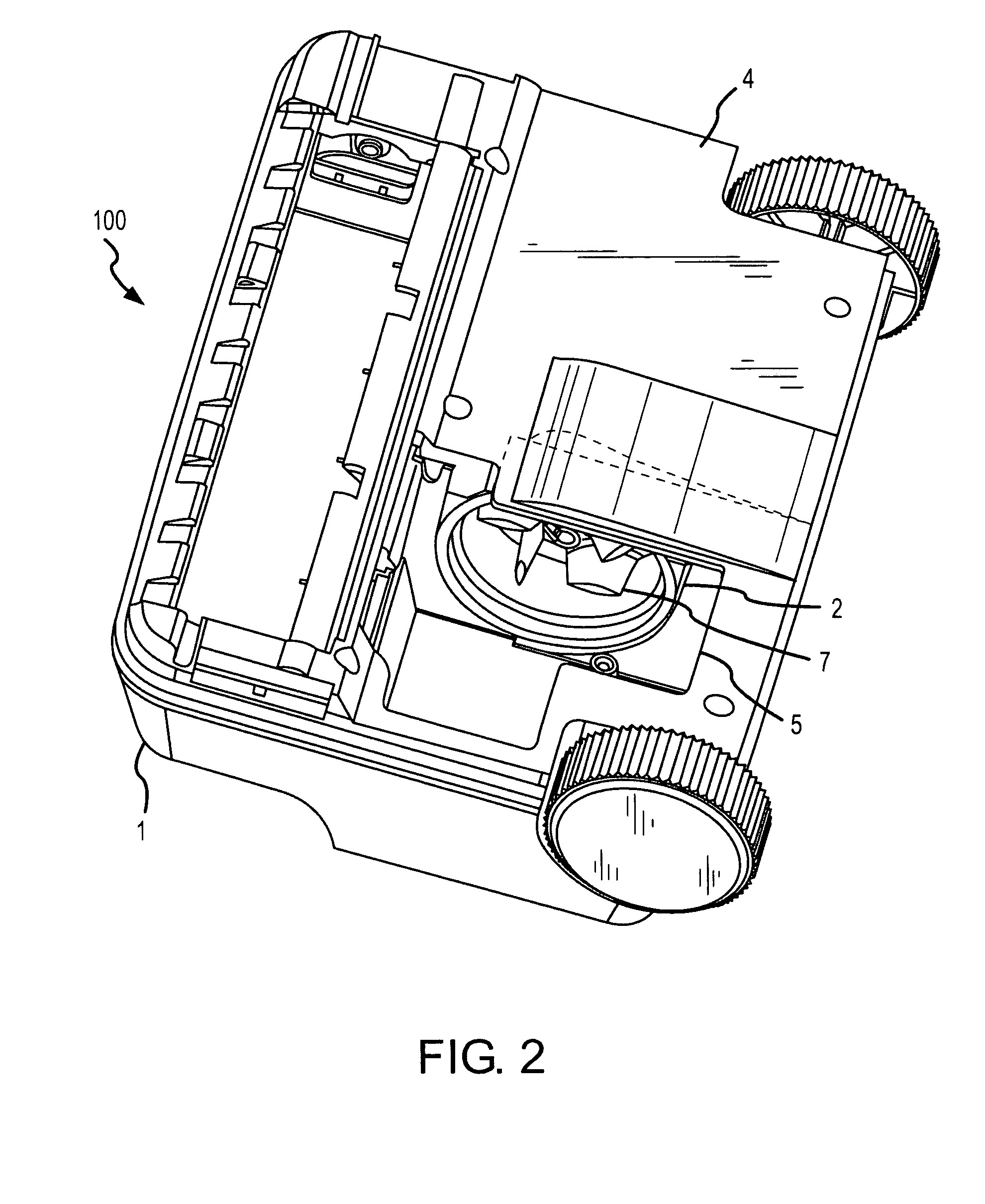
[0029]The blower housing 2 includes a motor or other rotational power source, an impeller (see FIGS. 2-4), and any necessary mounting and ducting apparatus. The blower housing 2 generates a vacuum and resulting airflow for the vacuum cleaner 100. In a dirty-air vacuum cleaner embodiment, the airflow containing dirt and debris picked up by th...


PUM


Abstract

A vacuum cleaner according to an embodiment of the invention includes a chassis, a fan unit including a blower housing mounted to the chassis and an inlet housing affixed to the blower housing, and a baseplate affixed to the chassis. An access aperture is formed in the baseplate. The access aperture extends at least partially over the fan unit. A door can be included in the baseplate. A bearing washer is positioned between the blower housing and the inlet housing and provides a substantially air-tight seal between the blower housing and the inlet housing. The inlet housing includes a bearing face, an inlet conduit portion, a slide flange, and a slide block. The slide block slides into and engages the slide flange and further slides into and engages the chassis of the vacuum cleaner.

Description

TECHNICAL FIELD[0001]The present invention relates to a vacuum cleaner, and more particularly, to a vacuum cleaner fan unit and an access aperture.BACKGROUND OF THE INVENTION[0002]A vacuum cleaner works by creating an airflow that can be directed to pick up dirt and debris. The airflow is typically created by a fan unit that includes a motor and an impeller. The dirt and debris in the airflow is filtered out and trapped in a bag for disposal.[0003]The fan unit is usually in the interior of the vacuum cleaner mechanism, and is relatively difficult to access. In the prior art, accessing the fan unit is typically difficult and time-consuming. For example, it is common to need to remove multiple fasteners and one or more panels (or other components) in order to access the fan unit. Then, removal of all or part of the fan unit in the prior art can additionally require removal of multiple fasteners and multiple parts.[0004]Access to and disassembly of the fan unit of a vacuum cleaner can ...

Claims


Application Information

Patent Timeline
Patent Type & Authority Patents(United States)
IPC IPC(8): A47L9/00A47L5/28A47L9/22
CPCA47L5/28A47L9/22
Inventor MOSHENROSE, PAUL A.REYNOLDS, CHARLES W.PATERSON, CHRISTOPHER M.IRBY, STEVE
Owner TECHTRONIC FLOOR CARE TECH LTD
Why Eureka
Try Eureka