
Storage receptacle

a technology for storage receptacles and metal receptacles, which is applied in the installation of lighting conductors, electrical apparatus casings/cabinets/drawers, coupling device connections, etc., can solve the problems of increasing the cost of fasteners, affecting the service life of the receptacle,

Inactive Publication Date: 2008-04-29
EDSAL MANUFACTURING COMPANY INC
View PDF7 Cites 12 Cited by
  • Summary
  • Abstract
  • Description
  • Claims
  • Application Information

AI Technical Summary

Benefits of technology

"The present invention is a storage receptacle made from a single piece of sheet metal that has front and rear ends, with flanges that are designed to securely attach the sides and bottom of the receptacle. The receptacle also has openings and tabs for easy assembly. Additionally, the invention includes a corner member that can be used to stack storage receptacles on top of each other. The technical effects of this invention include secure attachment of the sides and bottom of the receptacle, easy assembly, and stable stacking."

Problems solved by technology

However, some known metal receptacles may be subject to various disadvantages relative to plastic counterparts.
Any of the foregoing means for assembling the various components of the metal receptacles add cost to the receptacle.
Additionally, when discrete fasteners are used, the fasteners can increase cost and are also the source of aggravation where quantities are mishandled or the like.
Moreover, shipping of unitary units requires undue space waste, while later assembly of knock-down units is bothersome and can be attended by difficulties due to the noted fastener problem above or to out of tolerance manufacturing errors.

Method used


Image

  • Storage receptacle
  • Storage receptacle
  • Storage receptacle

Examples


Embodiment Construction

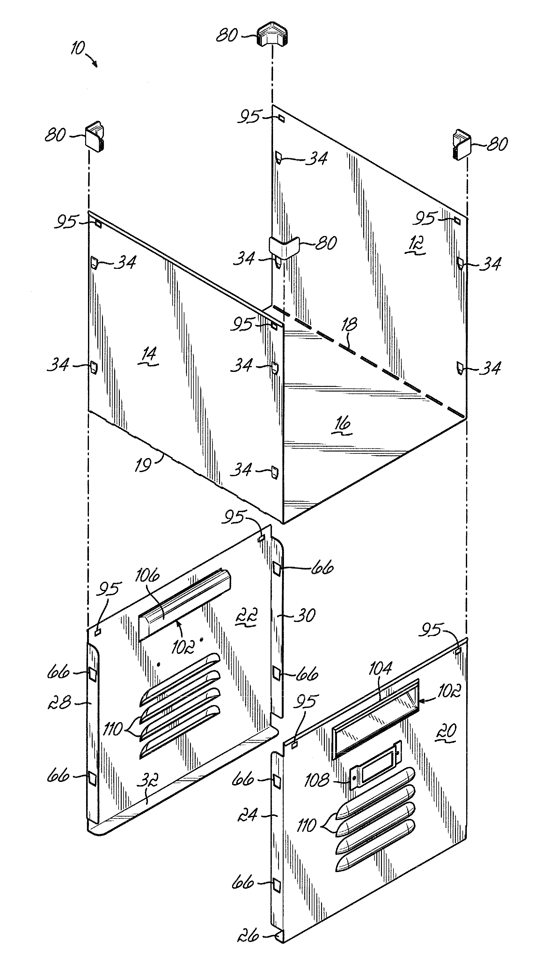
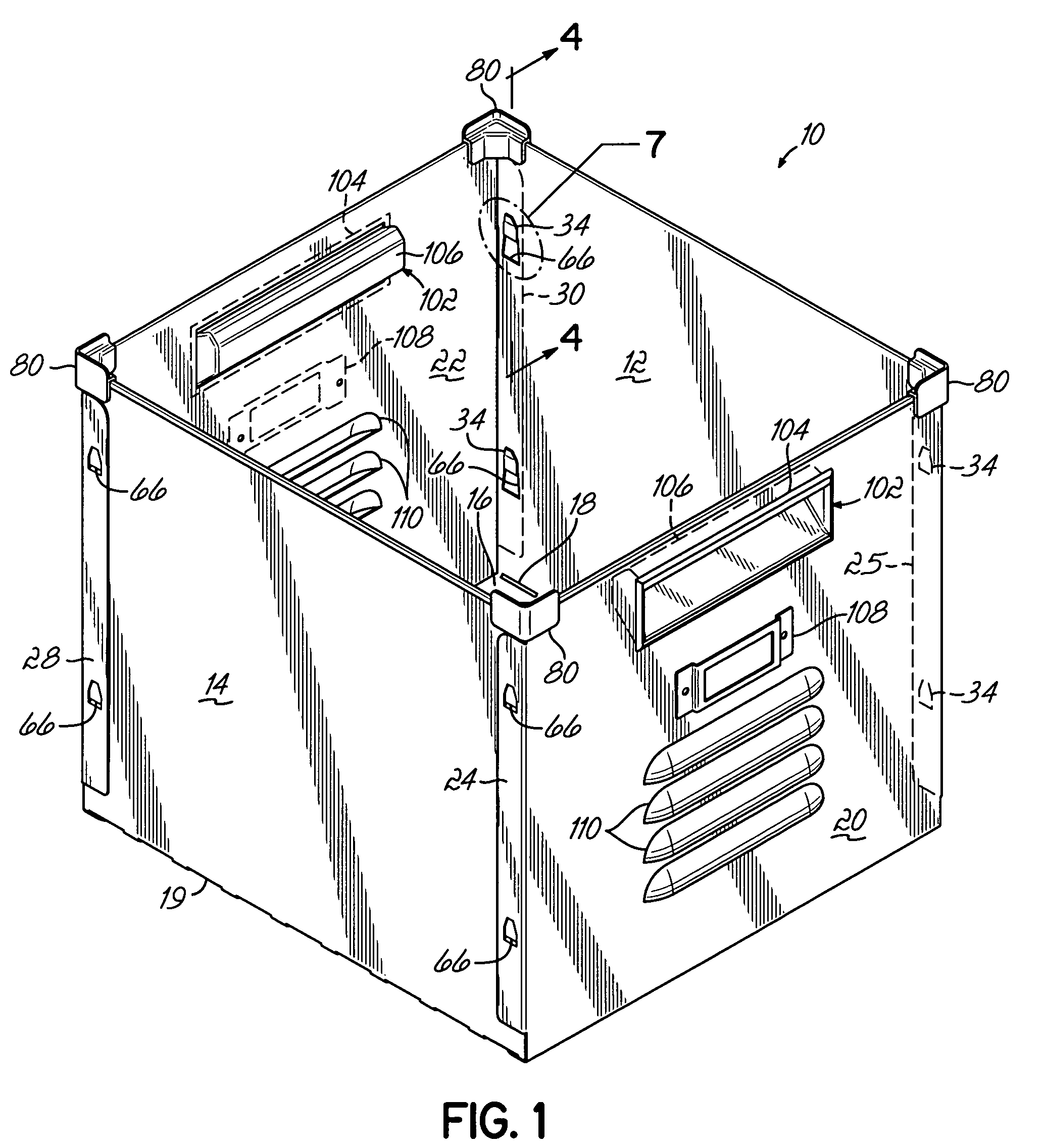
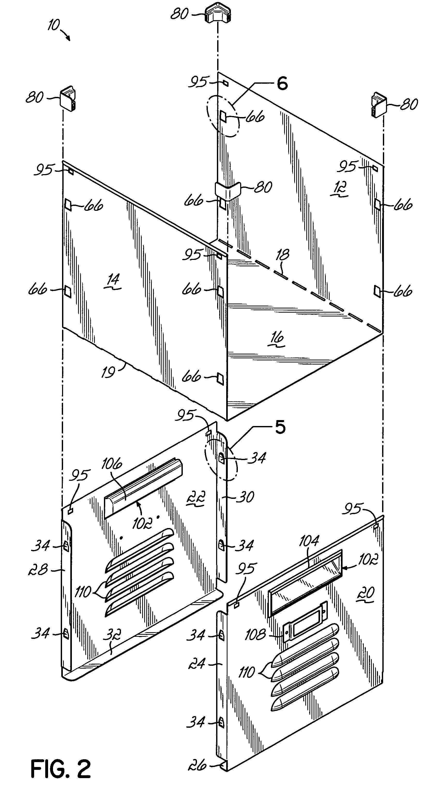
[0025]FIG. 1 is a perspective view illustrating a storage receptacle 10 according to the present invention and FIG. 2 is an exploded assembly view of the storage receptacle 10 shown in FIG. 1. Storage receptacle 10 includes a first side 12, a second side 14 and a bottom 16. As best seen in FIG. 2, the bottom 16 extends between and is integral with sides 12 and 14. In a preferred embodiment, side 12, bottom 16 and side 14 are formed as a unitary or one piece member from a single piece of material such as flat sheet metal which is bent along a first line 18 and a second line 19 at opposite edges of the bottom so that the sides 12 and 14 are substantially orthogonally disposed relative to the bottom 16. The one piece member has a forward edge along both sides and bottom and an opposed rearward edge along both sides and bottom opposite the forward edge.

[0026]Receptacle 10 further includes front 20 and rear 22 ends, also preferably made of metal. As subsequently discussed in greater deta...


PUM


Abstract

A storage receptacle is provided that has first and second sides and a bottom made as a unitary member from a single piece of sheet metal. The receptacle also includes front and rear ends, each coupled to the two sides and providing support for the bottom.

Description

CROSS-REFERENCES[0001]This application claims the priority benefit of U.S. Provisional Patent Application Ser. No. 60 / 640,791, “Shelving Connector”, filed Dec. 30, 2004, which is expressly incorporated by reference herein in its entirety.FIELD OF THE INVENTION[0002]This invention relates to storage receptacles and more particularly, to storage receptacles that may be used to store personal items.BACKGROUND OF THE INVENTION[0003]A wide variety of storage receptacles are known in the art, including those that are suitably sized and configured to store relatively small personal items, as opposed to relatively large household goods, for various applications. For instance, storage receptacles of this type may be used to hold various personal items such as wallets, watches, car keys, etc. while the owner of these articles is utilizing the facilities within a sports or health club, for instance. In these instances, the storage receptacle is typically placed within a locker, and may be refe...

Claims


Application Information

Patent Timeline
Patent Type & Authority Patents(United States)
IPC IPC(8): H02G3/08
CPCB65D7/28B65D7/30B65D21/0212B65D21/0224B65D25/2808Y10S248/906
Inventor COLLINS, JAMES E.WOJOTOWICZ, DAVID J.TROYNER, ANTHONY J.LISS, MITCHELL S.
Owner EDSAL MANUFACTURING COMPANY INC
Learn More