String fastening device

a fastening device and string technology, applied in the direction of fastenings, press-button fasteners, footwear, etc., can solve the problems of tangles of foreign objects in the exposed shifting lever, takes a lot of time to assemble the fastening device,

Active Publication Date: 2008-05-06
CHEN CHIN CHU
View PDF9 Cites 175 Cited by
  • Summary
  • Abstract
  • Description
  • Claims
  • Application Information

AI Technical Summary

Benefits of technology

[0006]The primary object of the present invention is to provide a string fastening device that includes a knob which can be pulled upward to disengage the knob from the reel so that the string can be loosened.
[0007]Another object of the present invention is to provide a string fastening device wherein no gear set is required and no shifting lever is protruded from outside of the device.

Problems solved by technology

However, there are too many parts in the fastening device which has a limited space to receive all the parts, so that it is difficult and takes a lot of time to assemble the fastening device.
Besides, the exposed shifting lever might tangle foreign objects, especially when the fastening device is installed on shoes.

Method used


Image

  • String fastening device
  • String fastening device
  • String fastening device

Examples


Embodiment Construction

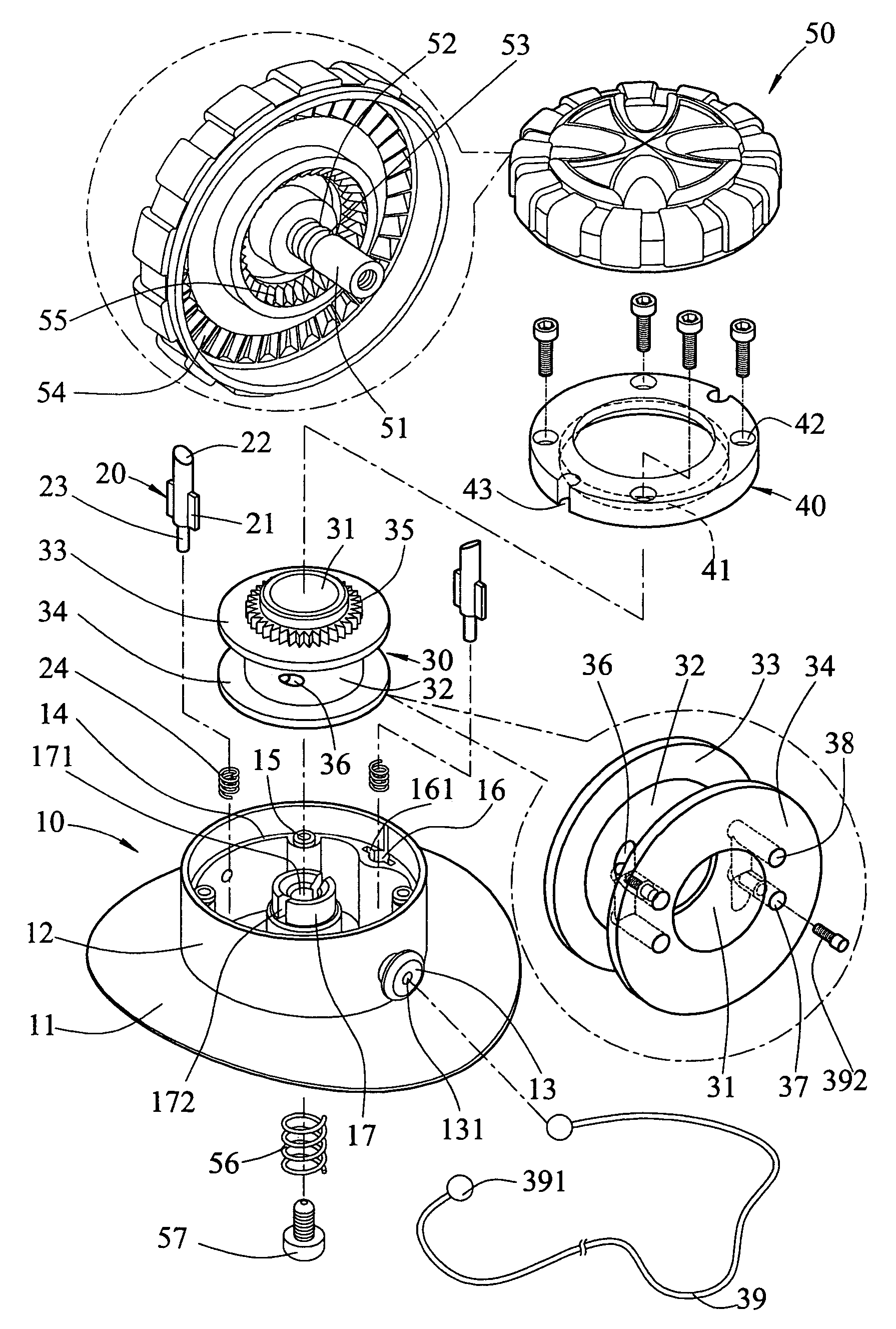
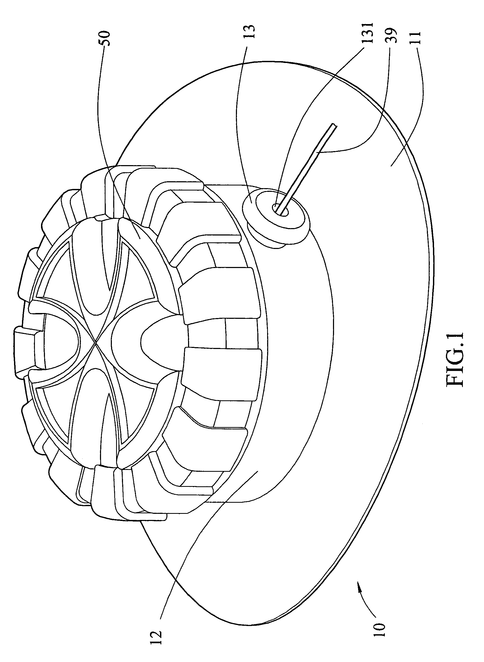
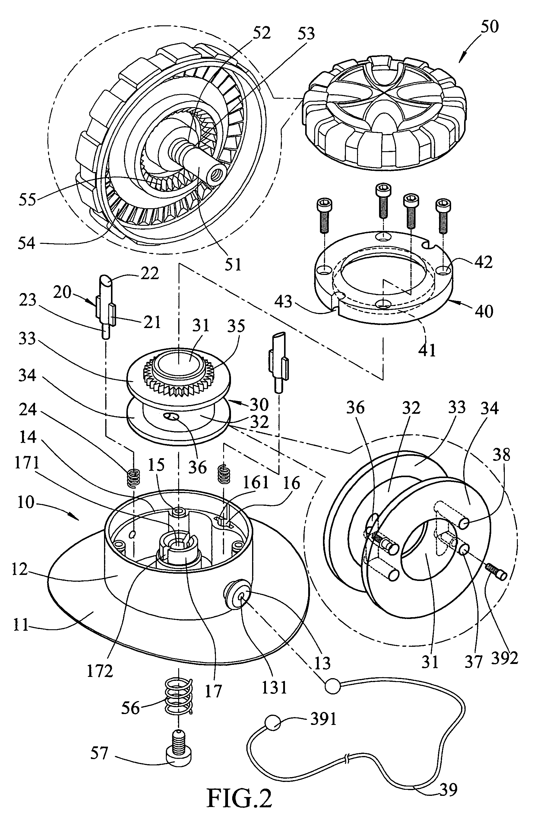
[0019]Referring to FIGS. 1, 2, 2-1, 3 and 4, the string fastening device 10 of the present invention comprises a base 11 with a tubular wall 12 on a top thereof and two protrusions 13 extend radially outward from the tubular wall 12 and each protrusion 13 has a hole 131 defined therethrough. A tube 17 extends from the top of the base 11 and is located in a space enclosed by the tubular wall 12. The tube 17 includes two slots 172 which open to a top of the tube 17 so as to form two parts on the top of the tube 17, and the two parts can be expandable outward and inward. A connection flange 14 extends inward from an inner periphery of the tubular wall 12 and a plurality of threaded holes 15 and two receiving holes 16 are defined in a top of the connection flange 14. The two receiving holes 16 each have two slits 161 which are in communication with the receiving hole 16 corresponding thereto. Two pawls 20 each have an insertion 23 on a lower end thereof which is axially movably inserted...


PUM


Abstract

A string fastening device includes a reel on which a string is reeled thereon and a toothed ring is connected to the reel. A knob has a shaft inserted into a tube extending from the base of the device and the reel is rotatably mounted on the tube. The knob has first teeth in an underside thereof and the first teeth are engaged with the toothed ring so that the reel is driven by rotation of the knob to tighten the ring. The knob can be pulled away from the reel to disengage the first teeth from the toothed ring so that the string can be loosened. The knob includes second teeth and the base has two pawls which limit the knob to rotate in one direction to drive the reel.

Description

FIELD OF THE INVENTION[0001]The present invention relates to a fastening device with a clutch device which controls the knob to be rotate in one direction to fasten the string.BACKGROUND OF THE INVENTION[0002]A conventional fastening device for tighten a string or shoe lace is shown in FIGS. 8 and 9 and generally includes a case 60 composed of a base 61 and a cover 62 between which a space 63 is defined and a ratchet device, a gear set 70 and a reel 80 are received in the space 63. A shaft 64 extends through the case 60, the ratchet device, the gear set 70 and the reel 80, and is connected to a knob 65 which is rotated relative to the case 60 so as to rotate the ratchet device which drives the gear set 70 and the reel 80. Two ends of a string 81 are fixed on the reel 80 and the string 81 is reeled around the reel 80. The ratchet device includes a ratchet wheel 71 and a pawl 66 is pivotably connected to the cover 62 and is cooperated with a torsion spring 661 so that the pawl 66 is n...

Claims


Application Information

Patent Timeline
Patent Type & Authority Patents(United States)
IPC IPC(8): B65H75/48A43C11/00
CPCA43C7/00A43C11/165Y10T24/2183
Inventor CHEN, CHIN CHU
Owner CHEN CHIN CHU
Why Eureka
Try Eureka