Lift mechanism for a seating device

a technology for lifting mechanisms and seating devices, which is applied in the direction of wheelchairs/patient conveyances, transportation items, refuse gathering, etc., can solve the problems of large effort and/or mechanical assistan

Inactive Publication Date: 2008-05-20
INTEGRATED VISION
View PDF12 Cites 13 Cited by
  • Summary
  • Abstract
  • Description
  • Claims
  • Application Information

AI Technical Summary

Benefits of technology

[0009]It is therefore an object of the present invention to provide a lift mechanism for incorporation into a vehicle that can readily secure and lift a wheelchair and / or other mobility seating device into the vehicle and be retained in a secure position therein.

Problems solved by technology

Those physically disabled people who are able to operate wheelchairs usually have the ability to operate vehicles as well, but have great difficulty entering and exiting vehicles.
Moreover, it is also a known challenge for wheelchair users, mobility device users, and those that assist them, to lift their wheelchair and / or other mobility device from the ground up into a vehicle or other mode of transportation, or to negotiate level changes within an architectural structure, such as a building.
As is known, a large amount of effort and / or mechanical assistance is required to assist or lift a person from ground level to a driving or riding position in a vehicle.
Moreover, significant effort and / or mechanical assistance is also required to lift or lower a person of physical disability from one elevation to another within any architectural building.
Such mechanisms also typically require major modification to the vehicle such as the addition of expensive, bulky and heavy equipment, which takes up a significant amount of space.
Furthermore, the loading and unloading of wheelchairs into and out of such modified vehicles by existing mechanisms is time consuming and often requires an operator, other than the handicapped individual, to operate the lifting mechanism.
It is also a challenge for users of mobility devices to lift their chair or device from the ground up into the vehicle or other mode of transportation, or to negotiate level changes in a building.
These platform type systems typically require a large amount of space and are therefore costly and disadvantageous.
Moreover, because these types of devices do not typically securely engage the wheels, movements can cause the wheelchair to move causing a less secure situation for the user.
For operation in an all terrain vehicle which causes significant movement of the vehicle in rough operation, this tie down does not allow as secure a seating situation as that experienced by non-disabled users in standard vehicle fixed seating.
This is thus not a system that can readily be used independently by the user.

Method used


Image

  • Lift mechanism for a seating device
  • Lift mechanism for a seating device
  • Lift mechanism for a seating device

Examples


Embodiment Construction

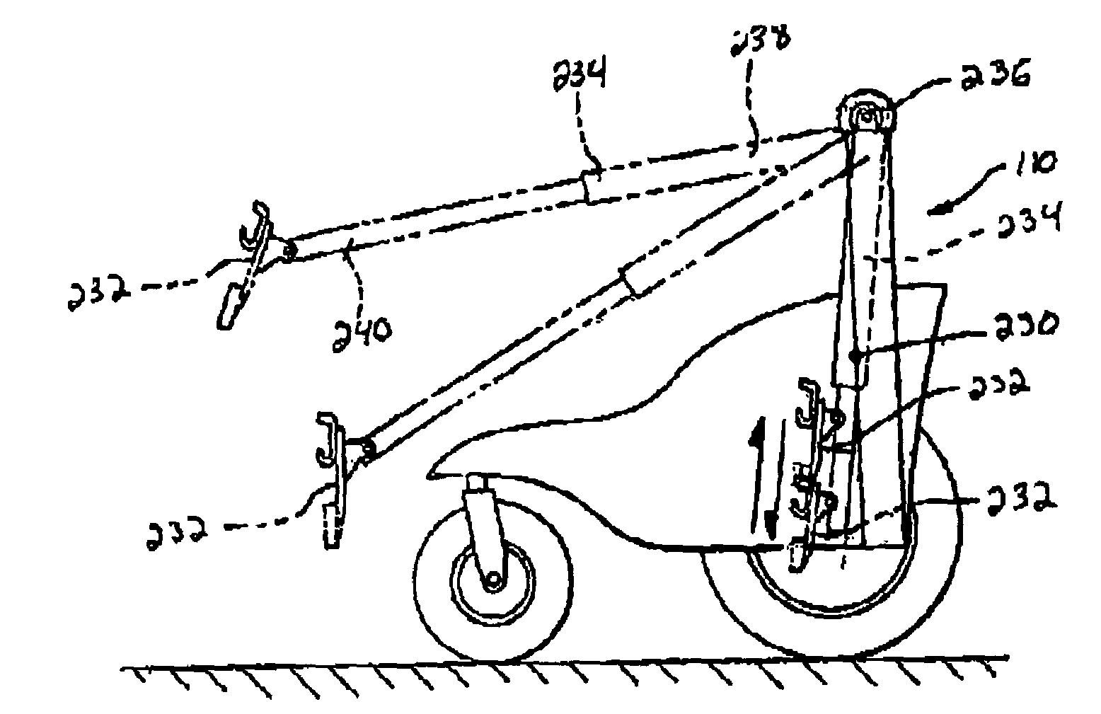
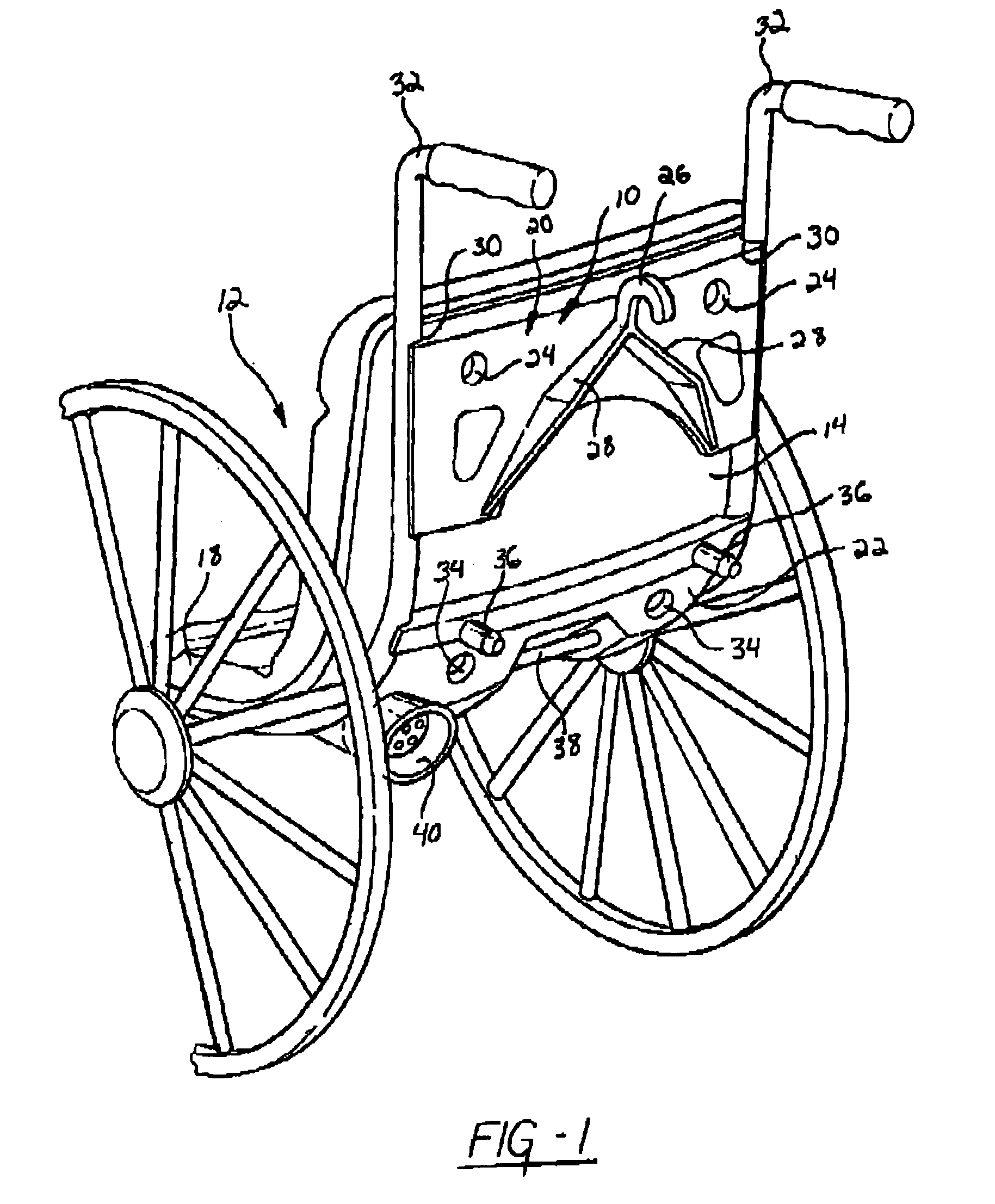
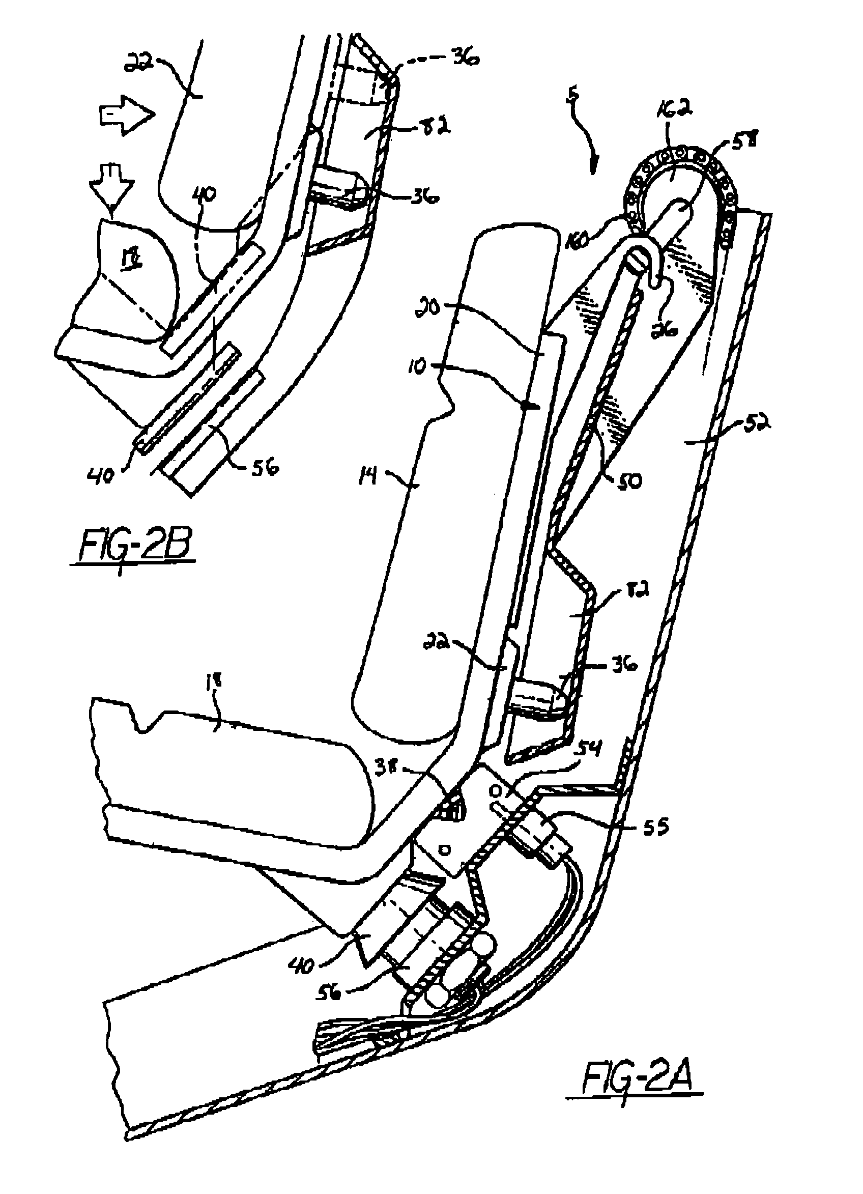
[0042]Referring now to FIG. 1, which illustrates a preferred coupling device 10, which is part of a coupling system 5 in accordance with the present invention. The coupling device 10 is preferably secured to the chair frame of a wheelchair 12. More preferably, the coupling device 10 is secured to the seat back 14 of the chair frame. It will be understood that the coupling device 10 may alternatively be secured to the seat bottom 18 of the chair frame. The coupling device 10 may be attached on a combination of the seat back 14 and the seat bottom 18 or a variety of other locations on the wheelchair 12 or combination thereof. However, the coupling device 10 is attached to the wheelchair 12 independently of the wheels. In other words, the coupling device 10 is secured to the wheelchair 12, such that it effects a rigid connection and does not interfere with any normal function of the wheelchair 12.

[0043]The coupling device 10 is preferably attached to the chair frame by welding. However...


PUM


Abstract

A lift mechanism for a chair device, such as a wheelchair, that is intended to engaged the frame of the wheelchair and lift and lower the wheelchair between a ground engaging position and an elevated position. The lift mechanism includes a lift arm having one end secured within and moveable with respect to a vehicle. The lift arm has another end which can extend outwardly of the vehicle to engage the chair device. The lift arm has a lift plate disposed adjacent the other end of the lift arm, which is intended to mate with or couple the frame of the wheelchair. The lift arm is in communication with an actuator which controls the movement of the lift arm between the ground engaging position and the elevated position. The lift mechanism utilizes a universal coupling system to effectuate elevation in vehicular transportation or architectural setting.

Description

CROSS-REFERENCE TO RELATED APPLICATIONS[0001]The present invention claims priority from U.S. Provisional Application Ser. No. 60 / 293,663, entitled “Chair Lift System For A Mobility Vehicle,” filed May 25, 2001; U.S. Provisional Application Ser. No. 60 / 293,673, entitled “Wheel Chair Lift Mechanism Into Mobility Vehicle,” filed May 25, 2001; U.S. Provisional Application Ser. No. 60 / 318,911, entitled “Wheelchair Attachment System,” filed Sep. 13, 2001; U.S. Provisional Application Ser. No. 60 / 317,008, entitled-“Personal Mobility Vehicle,” filed Sep. 4, 2001; and U.S. Provisional Application Ser. No. 60 / 293,849, entitled “Assisted Entry Seating Structure For A Mobility Vehicle,” filed May 25, 2001.TECHNICAL FIELD[0002]The present invention relates generally to the lifting of seating devices utilized by the physically handicapped or those in need of assistance from ground up into a vehicle. More specifically, the present invention relates to a lifting mechanism for lifting a wheelchair o...

Claims


Application Information

Patent Timeline
Patent Type & Authority Patents(United States)
IPC IPC(8): B60P1/00A01M31/02A61G3/04A61G3/06A61G3/08A61G5/10B60N2/24B66B9/08
CPCA01M31/02A61G3/063A61G5/104B60N2/245B66B9/08A61G3/0808A61G3/062B66B9/0853A61G2005/1054A61G2220/16Y10S414/134A61G7/1017A61G2220/145A61G5/1054
Inventor STRONG, RUSSELL W.
Owner INTEGRATED VISION
Why Eureka
Try Eureka