
Partial weight bearing suspension walker

a suspension walker and partial weight technology, applied in walking aids, physical therapy, gymnastics exercise, etc., can solve the problems of difficult rolling unaided, difficult to carry prior art units, and difficult to use on a smooth floor, so as to achieve low mass, minimal momentum effects, and carry partial weight

Active Publication Date: 2007-11-13
HOWLE EDWARD SAMUEL
View PDF15 Cites 70 Cited by
  • Summary
  • Abstract
  • Description
  • Claims
  • Application Information

AI Technical Summary

Benefits of technology

[0011]This invention provides an apparatus that can carry the partial weight of a patient during rehabilitation while walking on a treadmill or while walking on a floor with the device alone. The device is structurally strong enough to lift a patient yet light enough to be carried by one person. The invention folds to a smaller size for storage and transport and can be folded or unfolded by one person.
[0012]The invention can be used as a partial weight bearing walker due to its low mass and its minimal momentum effects. The device has wheels that can lock as a brake for use when lifting a patient out of a wheelchair or for use over a treadmill. The wheels can be locked to roll in one direction only for added stability when used as a suspension walker alone. The invention has a winch lifting system for lifting the patient to a standing position and for adjusting the amount of weight the patient bears on his / her legs. The preferred embodiment of the invention has a centrifugally activated failsafe mechanism that automatically stops the fall of the patient due to winch or rope failure or operator error while operating the winch. The device is also width adjustable and can be widened or narrowed to fit over treadmills or wheelchairs or through narrow doorways.

Problems solved by technology

The devices are normally used by patients while walking on a treadmill since the weight and the associated rolling friction of the devices makes them difficult to use on a smooth floor.
The units that are more mobile still require an assistant to help the unit roll since the weight of the unit plus the patient's weight make it difficult to roll unaided.
Those prior art units are difficult to transport and require the complete disassembly of the equipment and transport by truck or van.
Many units are necessarily wide to insure fitting over a treadmill or wheelchair but are often too wide to fit through most standard doorways.

Method used


Image

  • Partial weight bearing suspension walker
  • Partial weight bearing suspension walker
  • Partial weight bearing suspension walker

Examples


Embodiment Construction

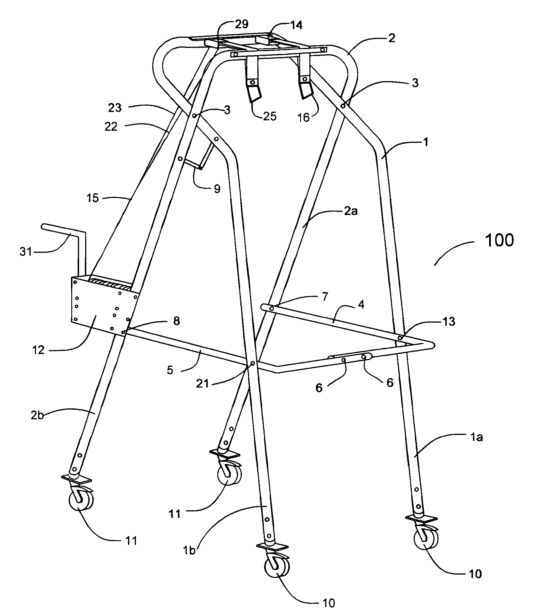
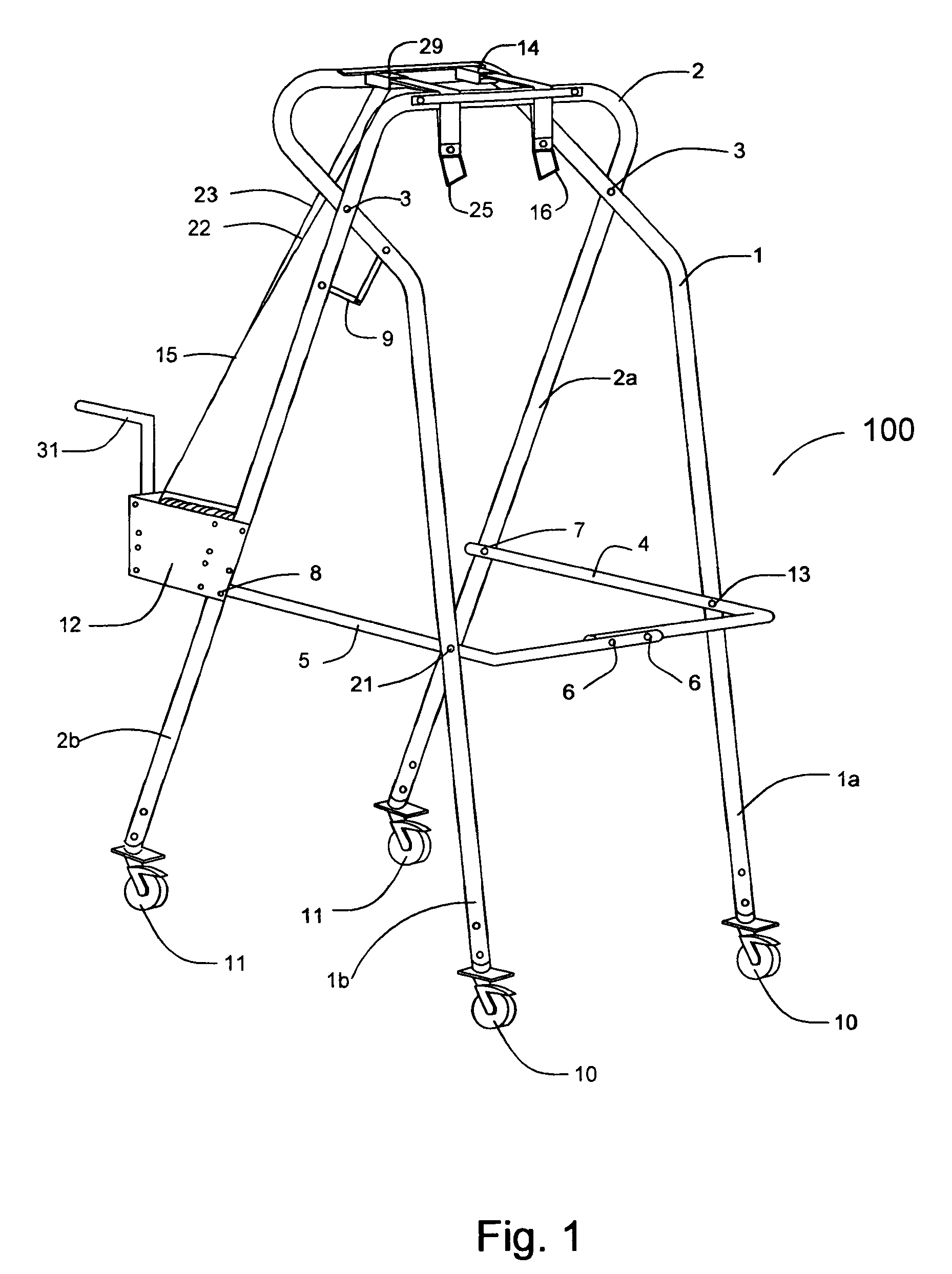
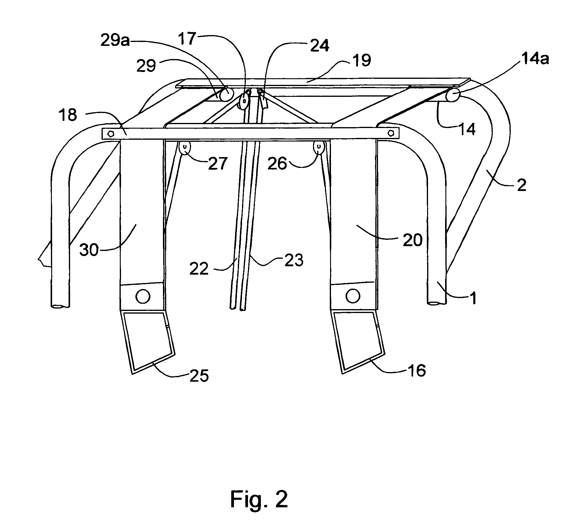
[0018]FIG. 1 shows a preferred embodiment of the weight bearing suspension walker 100. The forward frame 1 is pivotally attached to rear frame 2 with fasteners such as bolts at pivoting point 3. Forward frame 1 and rear frame 2 may also be pivotally attached with ball and socket joints, rods and clevis pins or other means such as are known in the arts to attach frames, tubing or bars in such a manner so to allow them to pivot in the same plane. Forward frame 1 has large diameter braking casters 10 attached to the bottom ends of each leg 1a, 1b of frame 1. The braking casters 10 swivel and can be braked to stop all rolling movement of the invention. Rear frame 2 has large diameter directional casters 11 attached to the bottom ends of each leg 2a, 2b of rear frame 2. The directional casters 11 swivel and can be locked in any steering direction compared to frame 2. Both braking casters 11 and directional casters 12 are attached to smaller diameter tubing that slides into forward frame ...


PUM


Abstract

A lightweight, foldable device for the partial weight bearing during walking and gait training is provided. The lightweight, partial weight bearing suspension walker is made from two frames that are pivotally attached and can be folded at the pivot point for storage or transport. The apparatus can be adjusted to fit over wide treadmills or wheelchairs and through narrow doors. The apparatus includes two fail-safe lift and support devices to insure patient safety in case of unintentional release by the operator.

Description

CROSS REFERENCE TO RELATED APPLICATIONS[0001]This application is entitled to the benefit and filing date of Provisional Patent Application 60 / 574,420 filed May 26, 2004. Applicant claims priority to Provisional Patent Application 60 / 574,420 filed May 26, 2005 pursuant to 35 USC paragraph 119e.STATEMENT REGARDING FEDERALLY SPONSORED RESEARCH OR DEVELOPMENT[0002]Not ApplicableBACKGROUND OF THE INVENTION[0003]1. Field of the Invention[0004]The present invention relates to a device for gait training for a walking impaired patient. More specifically the instant invention relates to a lightweight, foldable device that can partially support the weight of a patient while walking and can be adjusted wide enough to fit over treadmills or wheelchairs and can be adjusted narrow enough to fit through standard doorways.[0005]2. Discussion of Related Art[0006]Partial weight bearing gate trainers or unweighting systems are used by medical personnel during physical therapy to improve the mobility of...

Claims


Application Information

Patent Timeline
IPC IPC(8): A63B21/00
CPCA61H3/00A61H3/04A63B71/0009A61H3/008A61H2201/1652A61H2201/0161A63B22/02A63B2071/0018A63B2210/50A61H2201/0173A61H2201/0192A61H2201/1215A61H2201/163A61H2201/1635A61H2201/1642
Inventor HOWLE, EDWARD SAMUEL
Owner HOWLE EDWARD SAMUEL
Learn More