Method of connecting wire and terminal fitting

a technology of connecting wire and terminal, which is applied in the direction of electrical connection base, coupling device connection, manufacturing tools, etc., can solve the problems of reducing the performance of contact between the conductor portion and the terminal, and affecting the performance of the connection

Inactive Publication Date: 2008-05-20
YAZAKI CORP
View PDF22 Cites 55 Cited by
  • Summary
  • Abstract
  • Description
  • Claims
  • Application Information

AI Technical Summary

Benefits of technology

[0013]It is therefore an object of the present invention to provide a method of connecting a wire and a terminal fitting, in which wire elements are prevented from being cut and from becoming loose during ultrasonic welding, and at the same time a water stop treatment of a wire is effected.

Problems solved by technology

However, the above related wire-terminal connecting method has the following problems to be solved.
Secondly, the larger the pressing force, applied by the tip 59, is, and the higher the ultrasonic vibration frequency is, the shorter the time of heating and melting of the joining interface portion 65 is, and on the other hand there is encountered a problem that the plurality of wire elements 51c are more liable to become loose, and also are more liable to undergo damage such as cutting.
And besides, when a conductor portion of a thick wire (connected to a battery so as to supply a source current) or a conductor portion of a thin wire (connected to an on-vehicle part so as to feed a signal current) is kept in an exposed condition, waterdrops, dust and so on deposit on the conductor portion (conducting portion), which invites a problem that the performance of contact between the conductor portion and the terminal is lowered.

Method used


Image

  • Method of connecting wire and terminal fitting
  • Method of connecting wire and terminal fitting
  • Method of connecting wire and terminal fitting

Examples


Embodiment Construction

[0039]A preferred embodiment of the present invention will now be described in detail with reference to the drawings.

[0040]FIGS. 1 to 6 show one preferred embodiment of a wire-terminal connecting method of the invention.

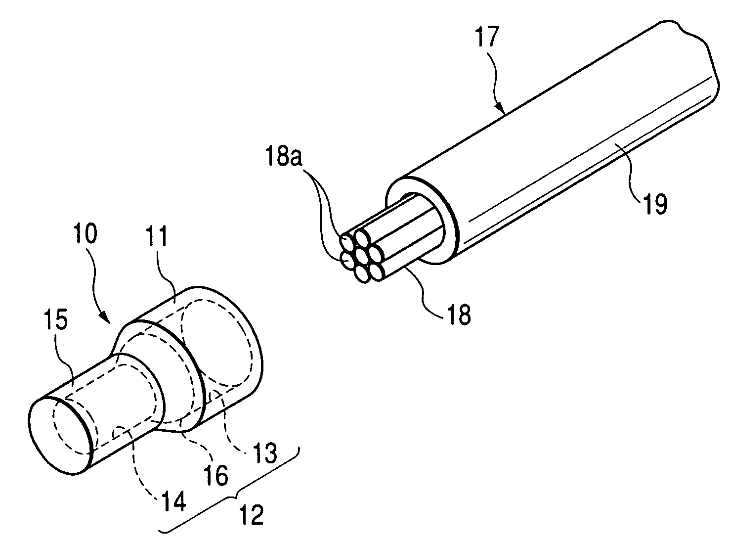
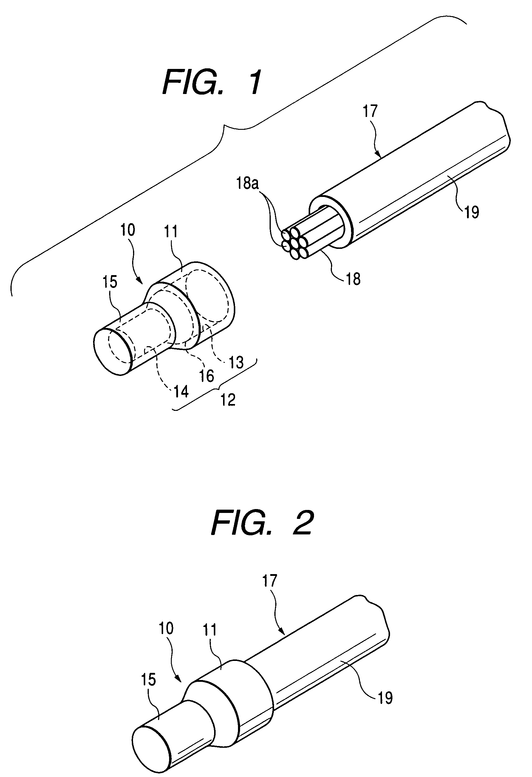
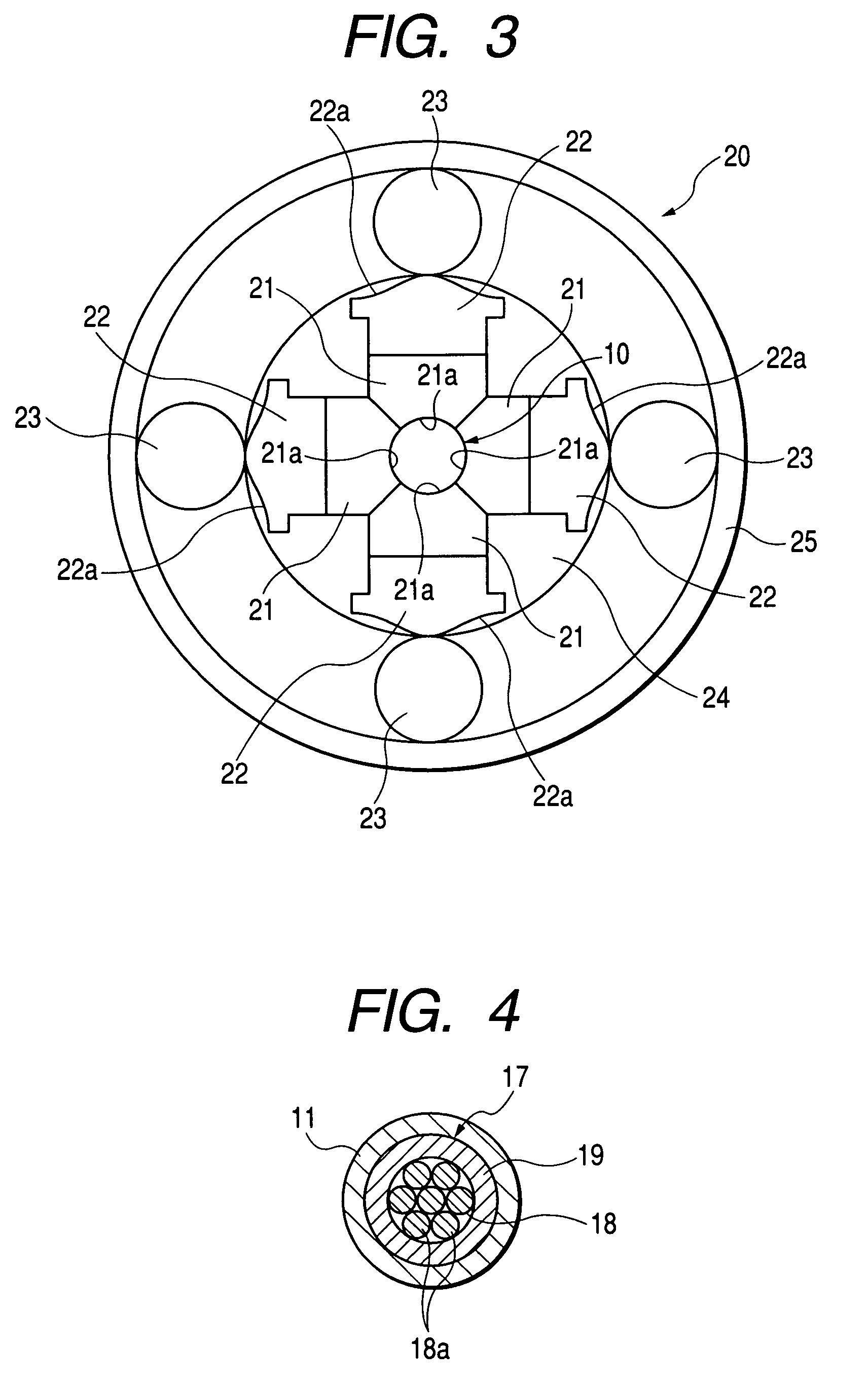
[0041]In FIG. 1, there are shown a connecting cap (connecting member) 10 made of an electrically-conductive material such as a copper alloy and an aluminum alloy, and an end portion of a wire 17 for insertion into an insertion hole 12 in the connecting cap 10.

[0042]The electrically-conductive connecting cap 10 is fitted on the end portion of the wire 17 (FIG. 2), and the outer periphery of the connecting cap 10 radially compressed by rotary swaging (described later), and the connecting cap 10 and an electrically-conductive terminal 40 are held between an anvil 31 and a tip 32 of an ultrasonic welding machine 30 (FIG. 6), and the connecting cap and the terminal are ultrasonically welded together.

[0043]The wire 17 includes a conductor portion 18 consisting of a plurali...


PUM

PropertyMeasurementUnit
point angleaaaaaaaaaa
tool angleaaaaaaaaaa
frequencyaaaaaaaaaa

Abstract

A method of connecting a terminal fitting and an electric wire, includes the steps of: providing a terminal fitting; providing an electric wire in which a core wire is covered with an insulating sheath; providing a conductive connecting member formed with an insertion hole; inserting the electric wire into the insertion hole of the connecting member; compressing the connecting member radially inwardly so as to caulk an inserted portion of the electric wire uniformly over a whole periphery thereof; and welding the connecting member and the terminal fitting by applying ultrasonic wave.

Description

BACKGROUND OF THE INVENTION[0001]This invention relates to a wire-terminal connecting method in which a wire for feeding a power source current or a signal current to an on-vehicle part is connected to a terminal by ultrasonic welding.[0002]One known related wire-terminal connecting method is disclosed in JP-A-54-43588.[0003]As shown in FIG. 7, this related wire-terminal connecting method is directed to the method of an invention in which a distal end portion 51a of a wire 51 is beforehand fixed into a semi-circular shape, and thereafter this fixed distal end portion 51a, together with a flat-type aluminum wire 55 (serving as a connecting wire), is held between a tip 59 and an anvil 60 of an ultrasonic welding machine 56, and an interface 65 (FIG. 8) of joining between the wire 51 and the flat-type aluminum wire 55 is heated and melted by vibrational energy, thereby effecting the welding.[0004]The distal end portion 51a of the wire 51 is fixed into the predetermined shape by the use...

Claims


Application Information

Patent Timeline
Patent Type & Authority Patents(United States)
IPC IPC(8): H01R4/02H01R4/20H01R11/28H01R43/02H01R43/04H01R43/058
CPCH01R11/28H01R4/20Y10T29/5327H01R43/0585
Inventor ONUMA, MASANORIFUJIMOTO, KEI
Owner YAZAKI CORP
Why Eureka
Try Eureka