Device for removing or inserting a fuse with an improved holding and release mechanism

a technology of holding and release mechanism and device, which is applied in the direction of pliers, electrical equipment, manufacturing tools, etc., can solve the problems of device gripping hooks being detached, the safety of fuse removal no longer guaranteed, and the engendering section or gripping hook provided on the device not staying correctly in the gripping profile of the fuse, etc., to achieve the effect of improving the versatility of the device, saving costs, and improving the force transmission

Inactive Publication Date: 2008-06-10
LISA DRAXLMAIER GMBH
View PDF18 Cites 34 Cited by
  • Summary
  • Abstract
  • Description
  • Claims
  • Application Information

AI Technical Summary

Benefits of technology

[0008]It is an object of the present invention to provide a removing device for electronic components that may be used in particular for fuses, and enables electronic components in very dense arrangements in difficult-to-access places, from a long distance, to be removed from or inserted in a plug-in board or a fuse-base in a fuse strip in a safe and problem-free way.

Problems solved by technology

When using the removing devices known from the prior art, a problem may arise in that, after the ends of the device have spread and the engaging sections provided at these ends have been brought into engagement with the fuse to be removed or inserted, for example with a gripping profile on the fuse, it is furthermore necessary to apply a force to the opposite end of the device in the longitudinal direction of the device in order to safely remove or insert the fuse from or into the fuse base.
A force of this type, after the device has been attached to the fuse, may cause the ends which are engaged with the fuse to spread again with the result that the engaging sections or gripping hooks provided on the device do not remain correctly in the gripping profile of the fuse.
Therefore, there is a probability of the device's gripping hooks to become detached from the fuse's gripping contour, and hence safe removal of the fuse is no longer guaranteed.
Due to the voltage applied to these components, they have to be protected from water or moisture, so that, under certain circumstances, these components are surrounded by side walls and a cover plate, and consequently only very small gaps remain between the components and the side walls protecting these components which makes access very difficult for an operator tasked with the replacement of these components.
Therefore, it is very difficult to remove and insert the components from or into the fuse-base with a conventional removing device in a safe and problem-free way.

Method used


Image

  • Device for removing or inserting a fuse with an improved holding and release mechanism
  • Device for removing or inserting a fuse with an improved holding and release mechanism
  • Device for removing or inserting a fuse with an improved holding and release mechanism

Examples


first embodiment

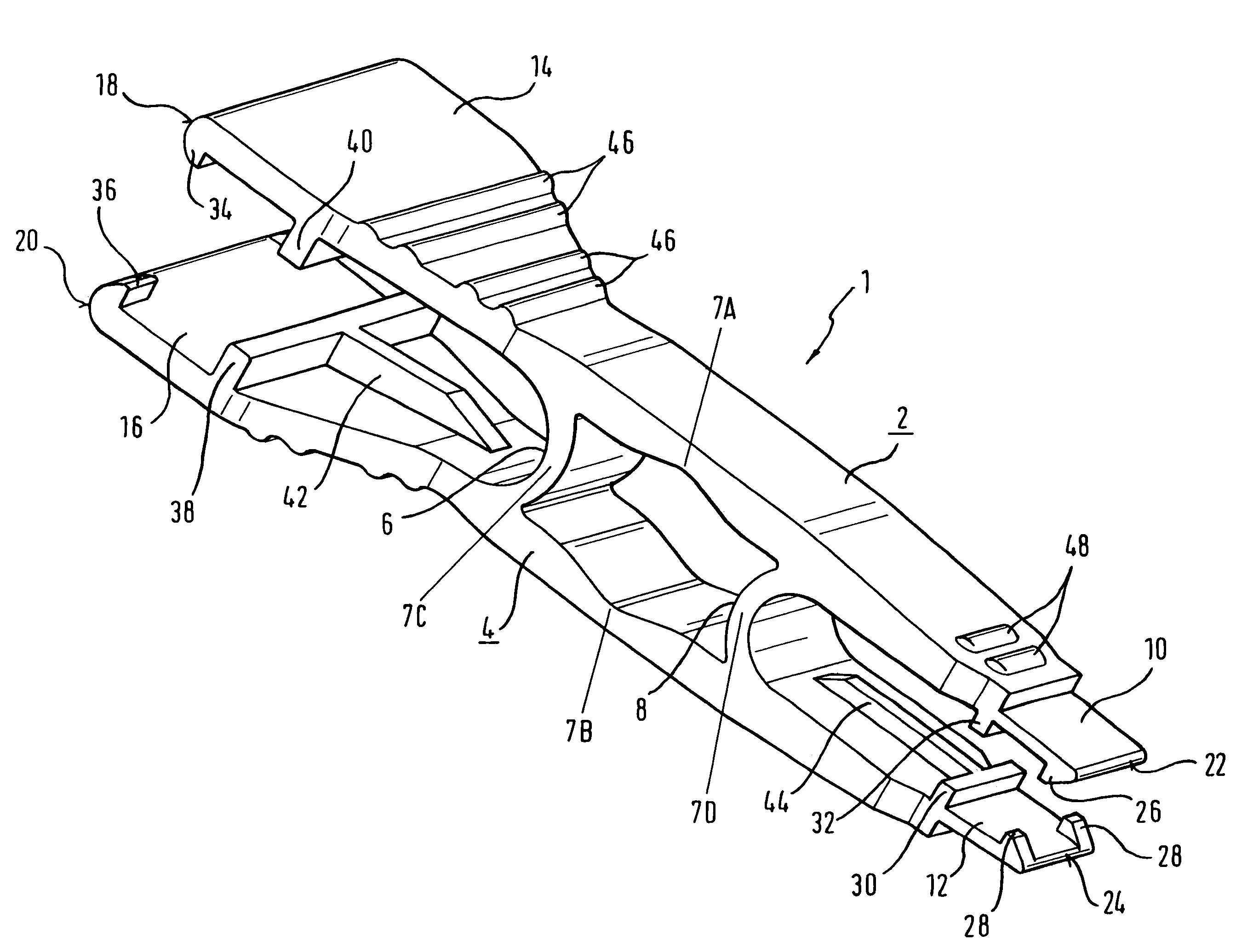
[0032]FIG. 1 is a perspective view of the removing device according to the invention. The removing device is generally indicated by reference number 1.

[0033]The device has two elongate arms 2, 4 which are substantially arranged parallel to each other. However, also conceivable are arrangements in which the arms are not arranged parallel to each other.

[0034]Arms 2, 4 are connected to each other in a central portion by two connecting sections 6, 8. The connecting sections 6, 8 of the first embodiment of the device according to the invention have a curved shape, whereby the distance of the connecting sections in the longitudinal direction of the arms is shortest in a central portion of the connecting sections. In other words, the first connecting section 8 is curved towards the left end of the device in FIG. 1, while the second connecting section 6 is curved towards the right end of the device in FIG. 1.

[0035]Outside the area of the arms 2, 4 defined by the connecting sections 6, 8, th...

second embodiment

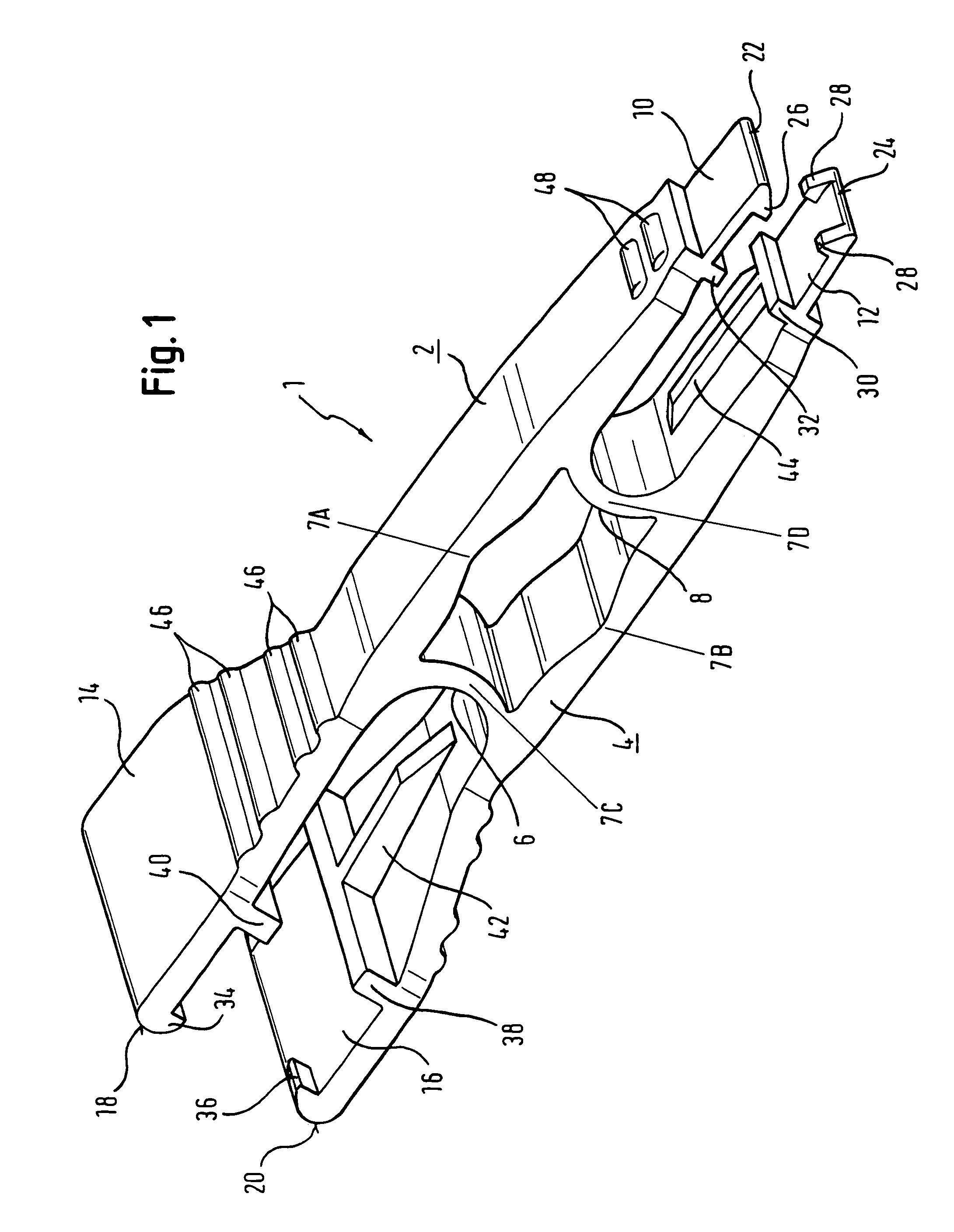
[0050]FIG. 2 shows the removing device according to the invention. However, here only those parts of this embodiment that differ from the embodiment shown in FIG. 1 will be described.

[0051]The second embodiment differs substantially from the first embodiment in the different arrangement of the articulated connections.

[0052]FIG. 2 shows six articulated connections 7A, 7B, 7C, 7D, 7E and 7F. The two articulated connections 7A, 7B hereby correspond to the articulated connections 7A, 7B identified with the same reference numbers in the first embodiment.

[0053]Due to the plate-shaped design of the connecting sections 6, 8, articulated connections 7C, 7E or 7D, 7F are arranged on their edges facing the internal surfaces of the arms 2, 4 which help to achieve the leverage. The application of a pressure force on the proximal end portion of the removing device, preferably on the portion having the ribs 46, causes the proximal half of the portion of the arms 2, 4 defined by the connecting sect...


PUM

PropertyMeasurementUnit
distanceaaaaaaaaaa
thicknessaaaaaaaaaa
elasticaaaaaaaaaa

Abstract

A device for removing or inserting a fuse, in particular an automotive safety fuse from or into a fuse base in a fuse strip. The device has a first and a second elongate arm each of which has a distal end and a proximal end whereby an engaging section that may be brought into engagement with the fuse is provided in the distal end portion of the first and the second arm. The device further includes a first connecting section connecting the first and the second arm to each other and provided proximally to the engaging section. The device has a second connecting section to connect the arms at a distance proximally to the first connecting sections and the first and second arms are articulated in such a way that reducing the distance between the two arms in the portion between the two connecting sections causes the distance between the distal ends of the two arms to increase, and that reducing the distance of the two arms in the portion proximal to the second connecting section causes the distance between the distal ends of the two arms to decrease.

Description

FIELD OF THE INVENTION[0001]The invention relates to a device for removing or inserting a fuse, in particular an automotive safety fuse, from or into a fuse-base in a fuse strip. The features in the preamble of claim 1 are known from DE 695 10 639 T2.PRIOR ART[0002]An extremely wide variety of devices for removing or inserting fuses of different DIN shapes from or into a fuse-base in a fuse strip is known from the prior art.[0003]For example, known from DE 695 10 639 T2 is a one-piece, plastic, injection-moulded removing device or puller with two elongate, plate-shaped arms connected by an elastic connecting section. The connecting section has a curved shape so that reducing the distance between the ends of the two arms at one end of the device causes the opposite arm ends to spread, thus bringing the claws provided on the internal surface of the arms into engagement with a fuse to be removed or inserted. The connecting section, therefore, represents an articulated connection connec...

Claims


Application Information

Patent Timeline
Patent Type & Authority Patents(United States)
IPC IPC(8): B25B9/00H01H85/02B25B9/02
CPCH01H85/0208Y10T29/53943
Inventor LUKASZYNSKI, TADEUSZFUSSL, PETERSALLER, ROBERT
Owner LISA DRAXLMAIER GMBH
Why Eureka
Try Eureka