Sanding device, and sanding assembly including the same

a sanding device and sanding assembly technology, applied in the direction of grinding/polishing hand tools, grinding machines, metal-working apparatuses, etc., can solve the problems of operator's inability to complete any intermediate activities, substantial markings on the area being worked, and time-consuming and very strenuous on the hands, particularly the fingers

Inactive Publication Date: 2008-06-10
A RICHARD TOOLS OUTILS A RICHARD
View PDF59 Cites 18 Cited by
  • Summary
  • Abstract
  • Description
  • Claims
  • Application Information

AI Technical Summary

Problems solved by technology

A major problem associated with the above-mentioned type of fastening device is that several turns of the nut about the pin are generally required to provide the necessary clearance to replace a worn-out sandpaper by a new sandpaper, and this is known to be very time-consuming and very strenuous on one's hands, particularly the fingers.
Furthermore, usually two hands are required to carry out such an operation, causing an operator to cease any intermediate activities and having to direct his or her attention onto the sandpaper replacement operation.
Another problem associated with the above-mentioned type of sanding tool is that if it is inadvertently flipped-over, when sanding, against the area being worked on, which is often drywall or plaster thereon, then the projections of the “rabbit ears” of the nuts of the fastening devices of the sanding tool will often cause substantial markings onto the area being worked on, which is very disadvantageous for obvious reasons.
Indeed, such damages are very often tedious and time-consuming to repair and such damages also prevent an optimal finish from being obtained.
Furthermore, it is also known that most conventional sanding devices are not considered optimal for certain applications, particularly for sanding corners, side edges and the like.

Method used


Image

  • Sanding device, and sanding assembly including the same
  • Sanding device, and sanding assembly including the same
  • Sanding device, and sanding assembly including the same

Examples


Embodiment Construction

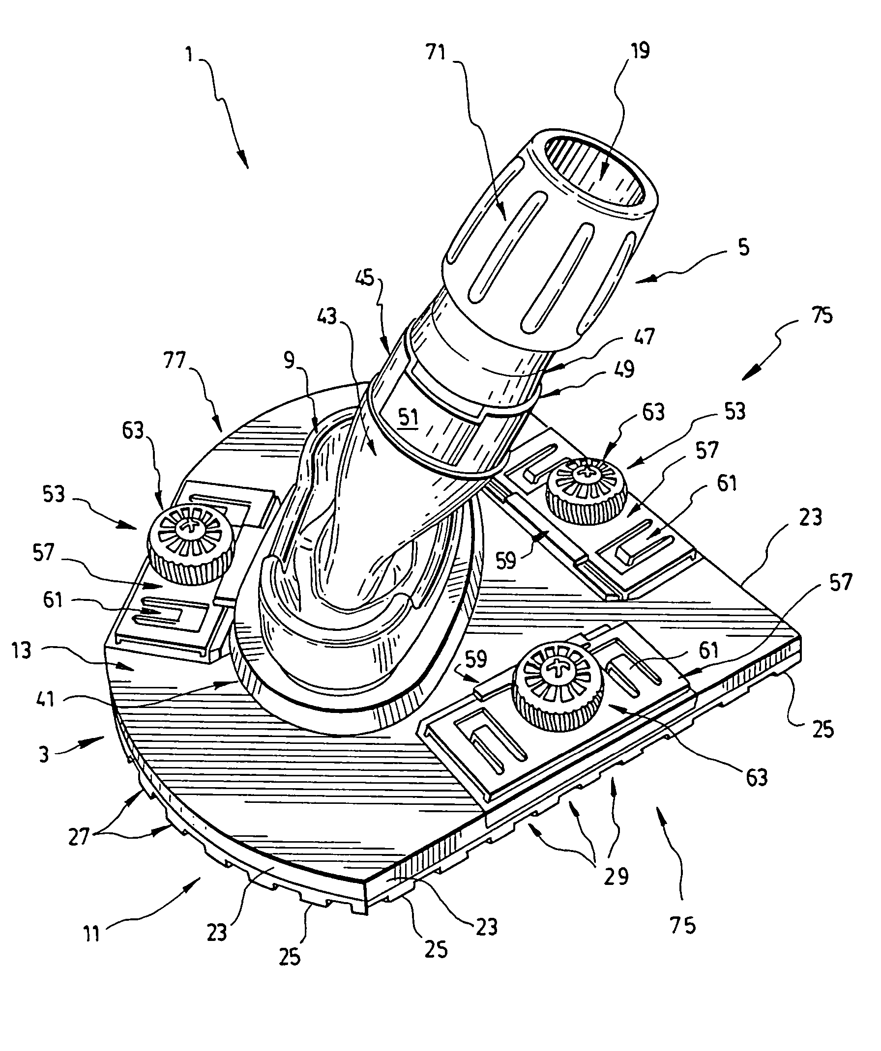
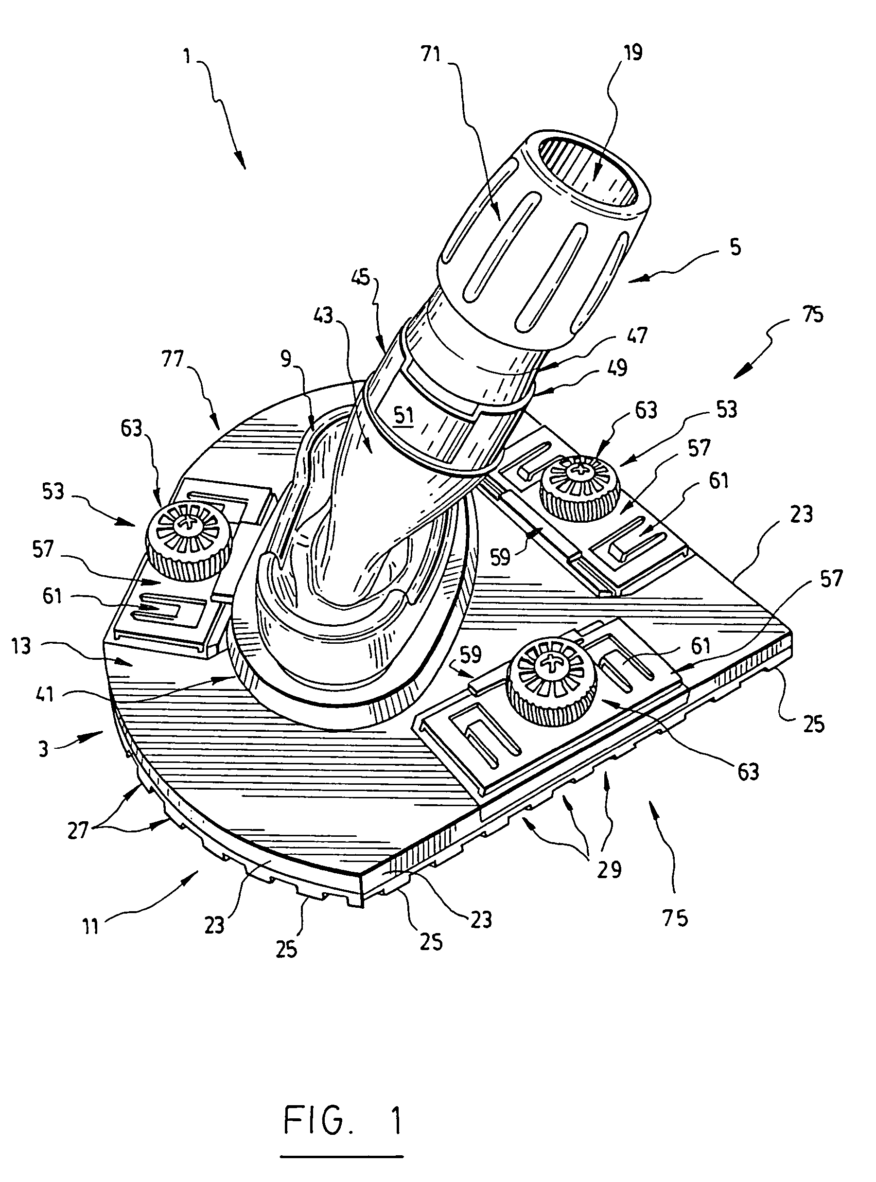
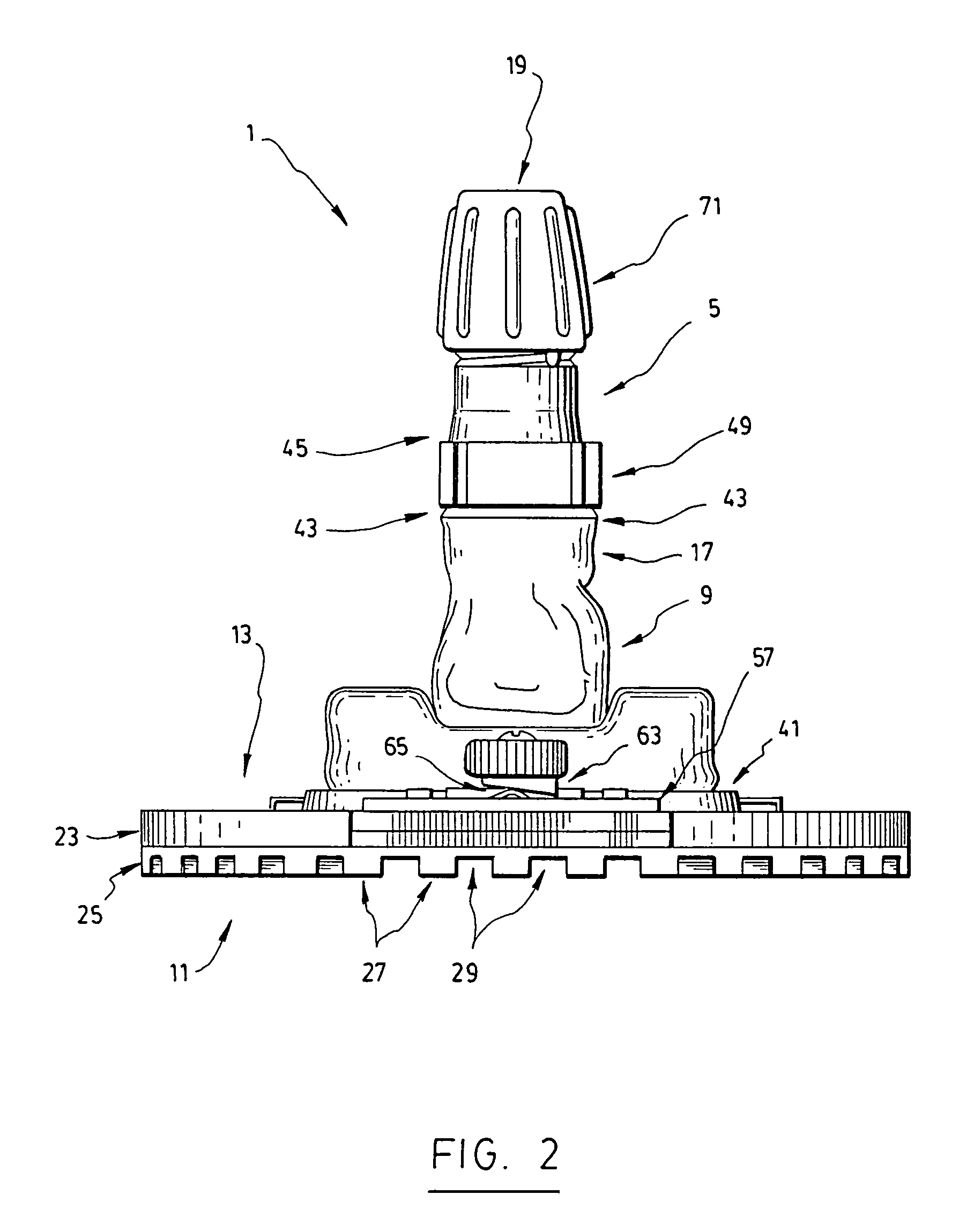
[0041]In the following description, the same numerical references refer to similar elements. The embodiments, geometrical configurations, materials mentioned and dimensions shown in the figures are preferred, for exemplification purposes only.

[0042]Moreover, although the present invention was primarily designed for use with a sanding paper / meshing for carrying out sanding applications, preferably in conjunction with a vacuum system and / or the like, it may be used with other objects and / or in other types of applications, as apparent to a person skilled in the art. For this reason, expressions such as “sanding”, “paper”, “meshing”, “vacuum”, etc., used herein should not be taken so as to limit the scope of the present invention and include all other kinds of objects and / or applications with which the present invention could be used and may be useful.

[0043]Moreover, in the context of the present invention, the expressions “tool”, “device”, “system”, “sander”, “unit”, “assembly”, as wel...


PUM


Abstract

A sanding device including a base plate, an evacuating tube, an articulated joint, and a sealing member. The base plate has a sanding surface and an opposite supporting surface, with an orifice extending therethrough for allowing the passage of particles sanded by the sanding surface. The evacuating tube has an inlet operatively connected to the supporting surface of the base plate, the inlet being positioned about the orifice of the base plate for receiving particles sanded by the sanding surface of the base plate, through the orifice thereof. The evacuating tube also has an outlet configured for operatively connecting to a vacuum system for evacuating sanded particles from the sanding surface through the orifice of the base plate via a suction effect provided by the vacuum system. The articulated joint is configured for operatively connecting the inlet of the evacuating tube to the supporting surface of the base plate, and has at least one pivot axis for enabling the evacuating tube to be articulated with respect to the base plate along various operating angles. The sealing member is operatively mounted onto the base plate for sealingly interconnecting the orifice of the base plate to the inlet of the evacuating tube. Also described is a sanding assembly provided with the above-mentioned sanding device.

Description

[0001]The present application claims priority of U.S. provisional patent application No. 60 / 748,167 dated Dec. 8, 2005 and of Canadian patent application No. 2,529,354 dated Dec. 8, 2005, the contents of which are both incorporated herein by reference.FIELD OF THE INVENTION[0002]The present invention relates to a sanding device, hereinafter referred to also as a “sanding tool”. More particularly, in its preferred intended use, the present invention relates to a sanding tool such as the ones used with vacuums and the like, and also relates to a vacuum / sanding assembly provided with such a sanding tool, and to a method of operating associated thereto.BACKGROUND OF THE INVENTION[0003]Known in the art are various tools used for sanding applications and other related tasks.[0004]The Assignee of the present application has developed several of such products, some of which are described in the following U.S. Pat. Nos. and industrial designs: D258,043; D263,277; D414,395; D431,993; D435,408...

Claims


Application Information

Patent Timeline
Patent Type & Authority Patents(United States)
IPC IPC(8): B24B27/08B24B23/00
CPCB24B23/00B24D15/00B24B55/10
Inventor PANFILI, LUIGI
Owner A RICHARD TOOLS OUTILS A RICHARD
Why Eureka
Try Eureka