
Mechanism for fastening a pivotal support in any direction

a technology of pivotal support and mechanism, which is applied in the direction of mechanical apparatus, machine supports, other domestic objects, etc., can solve the problems of inability to adjust the angle of the device, no optional fastening mechanism provided for the support, and undesired pivoting being especially significan

Inactive Publication Date: 2008-06-17
CHANG TA SHUO
View PDF10 Cites 55 Cited by
  • Summary
  • Abstract
  • Description
  • Claims
  • Application Information

AI Technical Summary

Benefits of technology

"The present invention provides a fastening mechanism for a suction cup that allows for easy attachment of an electronic device in any desired direction. The mechanism includes a receptacle with a pivotal ball and a support leg, and an inclined channel with a shank and a resilient member, such as a spring, that is compressively inserted into the ball and causes the shank to expand and insert into a recess on the ball, thereby fastening it. The receptacle can be spherical or have an arcuate inner surface. The technical effects of this invention include improved flexibility and versatility in attaching electronic devices to a suction cup, making it easier to adjust the device's orientation and improve its performance."

Problems solved by technology

This has the drawback of being impossible of adjusting an angle of the device.
However, there is no optionally fastening mechanism for the support provided.
Such undesired pivoting is especially significant after a period of time of use.

Method used


Image

  • Mechanism for fastening a pivotal support in any direction
  • Mechanism for fastening a pivotal support in any direction
  • Mechanism for fastening a pivotal support in any direction

Examples


Embodiment Construction

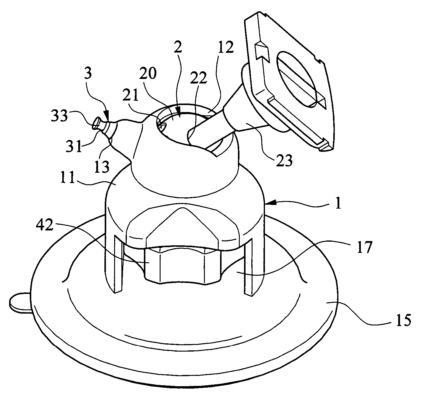
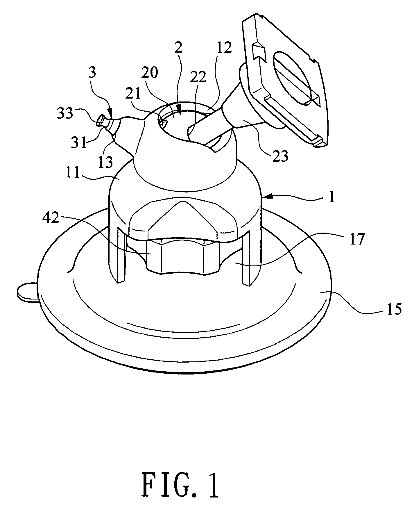
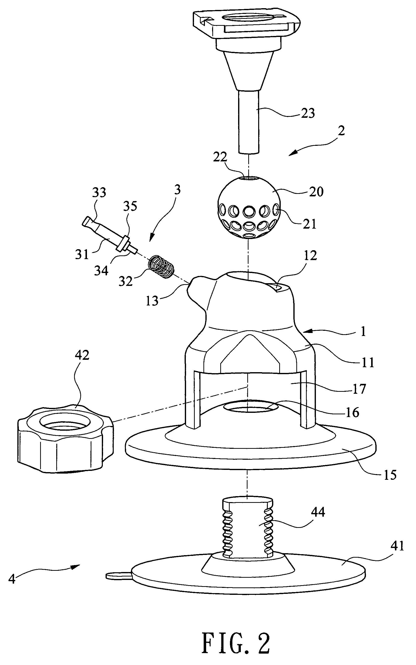
[0022]Referring to FIGS. 1 to 3, a fastening mechanism mounted on a suction cup in accordance with a preferred embodiment of the invention is illustrated. The suction cup comprises a bell 1 including a body 11, a substantially spherical receptacle (or arcuate cavity in other embodiments) 12 on an upper end of the body 11, an inclined channel 13 having one end open to the external and the other end in communication with the receptacle 12, an enlargement 14 in an intermediate portion of the channel 13, a bottom disc 15 having an inwardly extending rim, an internal space 17 open to both lateral sides of the body 11, and a central opening 16 formed on a top of the disc 15 and being in communication with the space 17; a pivotal support assembly 2 including a ball 20 pivotably provided in the receptacle 12, a plurality of recesses 21 formed on an outer surface of lower half of the ball 20, a hole 22 formed on a center of an upper half of the ball 20, and a leg 23 fixedly inserted in the h...


PUM


Abstract

A fastening mechanism is mounted on a suction cup including a pivotal ball in a receptacle and having surface recesses, a leg secured to the ball, and a channel open to both the external and the receptacle, the channel having an intermediate enlargement. The mechanism includes a shank in the channel and having an exposed end, a rod extended from the other end of the shank and inserted in the recess, a shoulder proximate the rod, and a resilient member compressed between the shoulder and an internal wall of the channel. Pulling the shank to clear the recess and compress the resilient member, pivoting the ball by rotating the leg until a predetermined angle thereof relative to the suction cup is obtained, and releasing the shank to cause the compressed resilient member to expand to push the shoulder will insert the rod in the adjusted recess and fasten the ball.

Description

BACKGROUND OF THE INVENTION[0001]1. Field of Invention[0002]The present invention relates to fastening mechanism incorporating suction devices and more particularly to a spring-biased mechanism for fastening a pivotal support formed on a member (e.g., suction cup) in any direction.[0003]2. Description of Related Art[0004]Conventionally, a portable electronic device (e.g., mobile phone, PDA (Personal Digital Assistant), smartphone, DVD, VCD, LCD, or the like) is fixedly mounted on a place (e.g., instrument board of an automobile) by securing to a fixed cradle. This has the drawback of being impossible of adjusting an angle of the device.[0005]As disclosed in the art, a pivotal support secured to cradle is for holding a mobile phone in a desired using position. However, there is no optionally fastening mechanism for the support provided. Thus, the support may pivot after being positioned. Such undesired pivoting is especially significant after a period of time of use. Thus, a need for...

Claims


Application Information

Patent Timeline
Patent Type & Authority Patents(United States)
IPC IPC(8): F16B47/00
CPCF16C11/106F16M11/041F16M11/14F16M13/00F16M13/022F16B47/00F16M2200/024
Inventor CHANG, TA SHUO
Owner CHANG TA SHUO
Learn More