Check patentability & draft patents in minutes with Patsnap Eureka AI!

Steering wheel with non-rotating airbag

a technology of driver airbag and steering wheel, which is applied in the direction of pedestrian/occupant safety arrangement, vehicle components, electric/fluid circuit, etc., can solve the problems of time-consuming mounting operations, high production costs, and inability to rotate the steering wheel ring portion uniformly, and achieves the effect of simple manufacturing and assembly

Inactive Publication Date: 2008-06-24
KEY SAFETY SYST
View PDF7 Cites 22 Cited by
  • Summary
  • Abstract
  • Description
  • Claims
  • Application Information

AI Technical Summary

Benefits of technology

"The present invention provides a steering wheel with a stationary central portion that can be easily mounted on existing steering columns without needing to be re-designed. The steering wheel can also be directly connected to a steering shaft in a traditional way. Additionally, the steering wheel has a static, non-rotating driver airbag module that can be adapted to different needs and requirements. Overall, this invention offers an economical, reliable, and simple solution for upgrading the steering system of vehicles."

Problems solved by technology

Prior art assemblies provided with gears usually have a complicated structure that leads to high production costs and time-consuming mounting operations.
If one of the static driver airbag components has dimensions different from what is specified, a non-uniform rotation of the steering wheel ring portion may occur, for example due to the imperfect matching between the gears.
A drawback of such solutions is that a tensioning device has to be provided for the belts.
Moreover the belts loose their mechanical properties in time as they undergo mechanical and thermal stresses.
Generally, solutions based on a plurality of shafts are complicated and expensive.
Duplication of the steering shaft facilitates passing the airbag module wiring harness easily inside the steering wheel column, but requires accurate design and assembly, expensive mechanical components and eventually electronic devices.
Moreover, traditional assemblies provided with a plurality of gears or shafts are normally cumbersome.

Method used


Image

  • Steering wheel with non-rotating airbag
  • Steering wheel with non-rotating airbag
  • Steering wheel with non-rotating airbag

Examples


Embodiment Construction

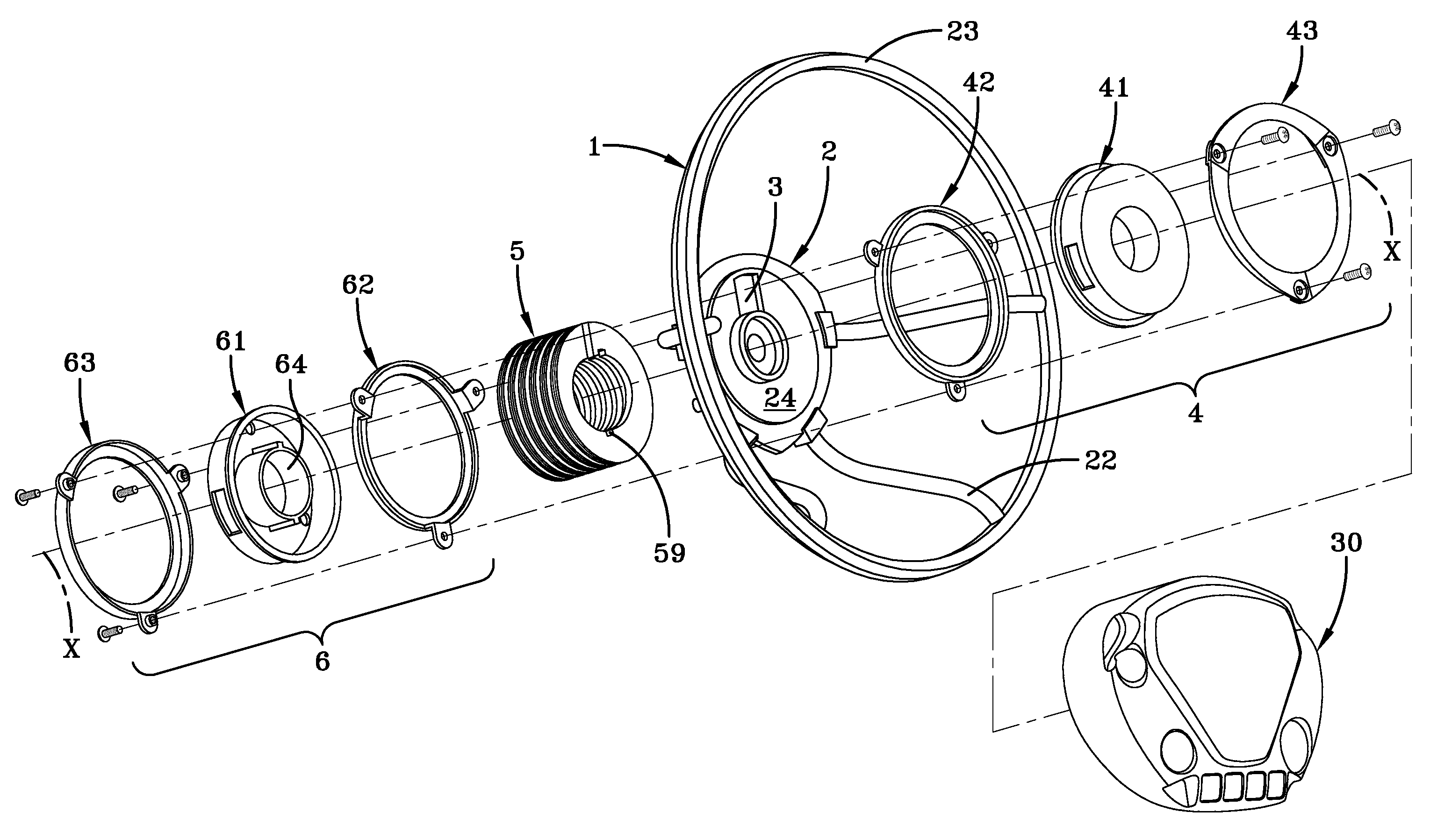
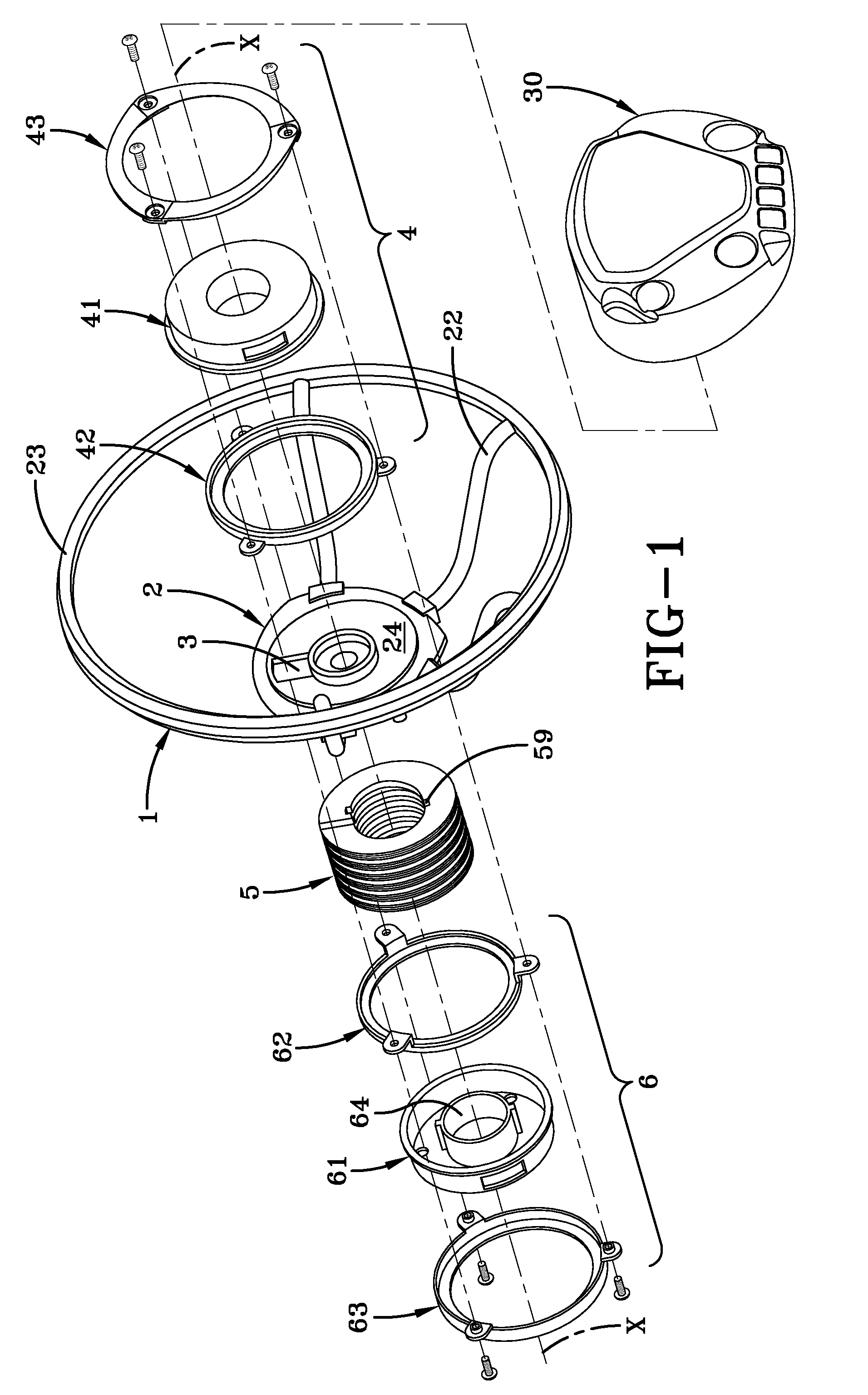
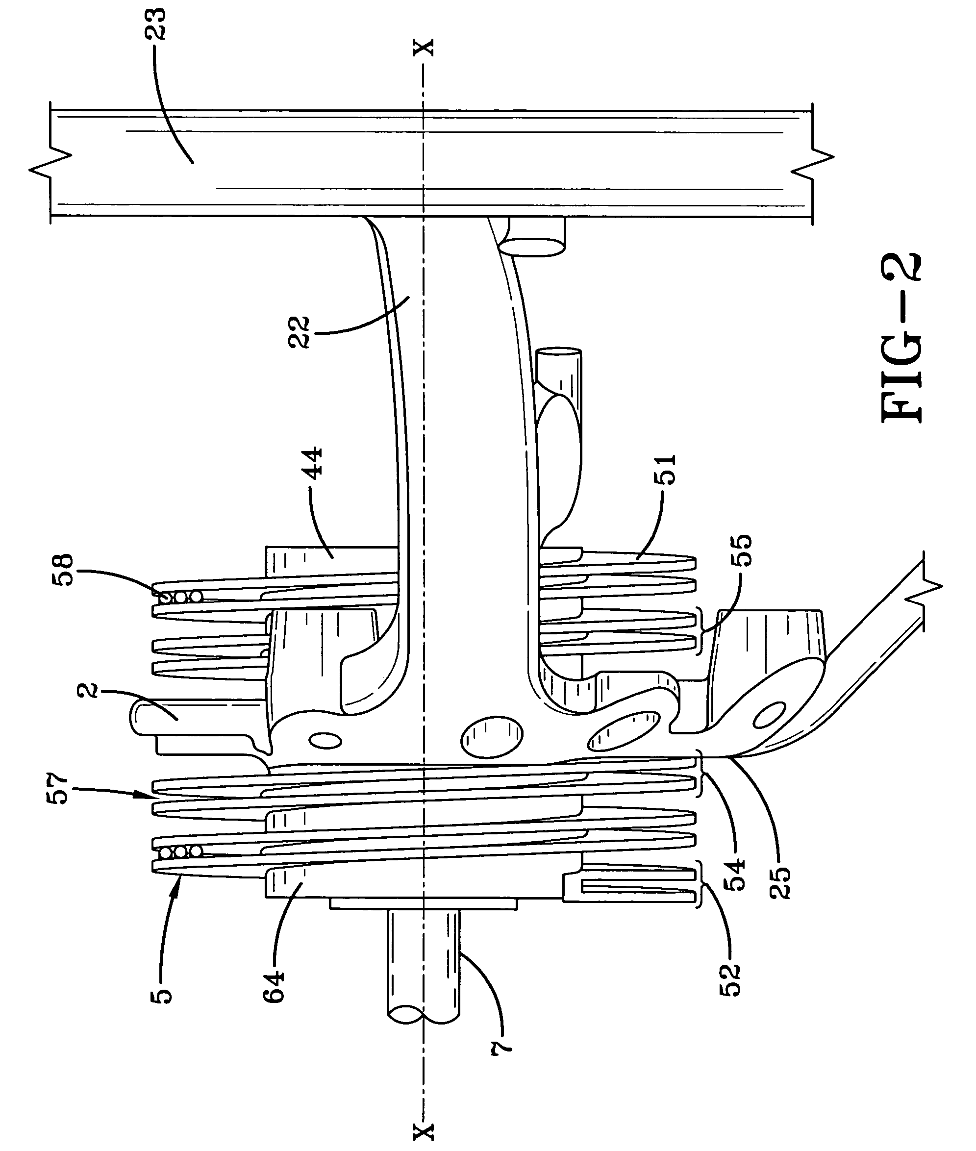
[0022]An exploded view of a steering wheel according to the present invention is shown in FIG. 1. The steering wheel comprises an armature 1 that may be of a traditional type having a hub 2, one or more spokes 22 and a rim 23. The hub 2 is fixable to a steering wheel shaft 7 (FIG. 2) along a common axis of rotation X-X. The hub is provided with a through opening 3 that connects a side 24 of the hub 2 that will be proximal with a vehicle driver with an opposite side 25 of the hub 2 that will be distal from a vehicle driver, i.e. the side proximal a vehicle steering column. In the embodiment shown in FIG. 1, the opening or aperture 3 is positioned on the hub 2 spaced radially apart from the axis of rotation X-X of the steering wheel. The hub can be directly fixed to a steering shaft in a traditional way, for instance by coupling the shaft to the centre of the hub. Thus the steering wheel according to the present invention does not need the vehicle steering column to be re-designed. Ro...


PUM


Abstract

The present invention relates to a steering wheel having a stationary hub mounted portion. The steering wheel has an armature with a hub and is coupled to a vehicle steering shaft. The hub is provided with an opening through which a coiled element passes. A non-rotating housing is assembled with the hub. The coiled element connects the non-rotating housing to a stationary component of the vehicle. The coiled element screwing or unscrewing itself to or from the hub via the opening when the steering wheel is rotated.

Description

FIELD OF THE INVENTION[0001]The present invention relates to a steering wheel having a stationary hub mounted portion, in particular to a steering wheel having a non-rotating driver airbag module.BACKGROUND OF THE INVENTION[0002]A typical driver airbag module is mounted on a vehicle steering wheel usually fixed to a hub, which in turn is coupled to a steering shaft. Consequently a driver airbag rotates in unison with the steering wheel. Since the deployment of the airbag may occur at different rotational orientations of the steering wheel with respect to the vehicle driver, the driver airbag has to be circular or symmetrical shaped to provide always the same shape of protection surface to the driver.[0003]In some motor vehicles, for instance sport cars, the maximum diameter of the airbag is limited by the high inclination of the windscreen and the front door jambs. Recently, steering wheel assemblies have been provided that allow the driver airbag module to remain in a stationary po...

Claims


Application Information

Patent Timeline
Patent Type & Authority Patents(United States)
IPC IPC(8): B60R21/16
CPCB60R16/027B62D1/105
Inventor RIDOLFI, ROBERTOPOLI, VALERIORIDOLFI, ADOLFO
Owner KEY SAFETY SYST
Features
  • R&D
  • Intellectual Property
  • Life Sciences
  • Materials
  • Tech Scout
  • Unparalleled Data Quality
  • Higher Quality Content
  • 60% Fewer Hallucinations
Learn More