Inflatable penile prosthesis with volume displacement materials and devices

a technology of volume displacement and prosthesis, which is applied in the field of implantable penile prosthesis, can solve the problems of inflating the prosthesis, reducing the volume of the prosthesis, and reducing so as to reduce the amount of fluid needed to change the condition of the device, reduce post-surgical scarring, and reduce the effect of fluid volum

Active Publication Date: 2008-06-24
BOSTON SCI SCIMED INC
View PDF16 Cites 46 Cited by
  • Summary
  • Abstract
  • Description
  • Claims
  • Application Information

AI Technical Summary

Benefits of technology

[0005]The present invention provides certain advantages relating to the reduced volume of fluid that must be transferred within a system to inflate and deflate implantable penile prostheses. With the devices and methods of the present invention, it may be possible for the system to include a relatively small reservoir for holding the smaller amount of fluid required for the inflation and deflation processes. This is accomplished using a variety of different elongated structures, each of which can be positioned within a cylindrical prosthesis to occupy a portion of the interior cavity of the structure. In other words, when the interior cavities of the devices have at least a portion of their volumes filled with material, the amount of fluid to change the condition of the device is reduced. The use of such volume-occupying devices may provide the further advantages of reducing post-surgical scarring, preventing or eliminating post-surgical shortening or shrinkage of the penis, enhancing patient comfort, and providing a more natural feel to the flaccid penis.

Problems solved by technology

This results in the inflation of the prostheses and produces rigidity for a normal erection.
In many of these penile implant devices, the prostheses will be in a relatively collapsed state or condition when deflated and will not again regain significant rigidity until the penile implant device is reactivated, thereby causing at least partial reinflation of the cylinders.
In many cases, when the prostheses are in their collapsed state (i.e., the flaccid state of the penis), they may not provide enough support to give the patient a natural feeling of fullness.

Method used


Image

  • Inflatable penile prosthesis with volume displacement materials and devices
  • Inflatable penile prosthesis with volume displacement materials and devices
  • Inflatable penile prosthesis with volume displacement materials and devices

Examples


Embodiment Construction

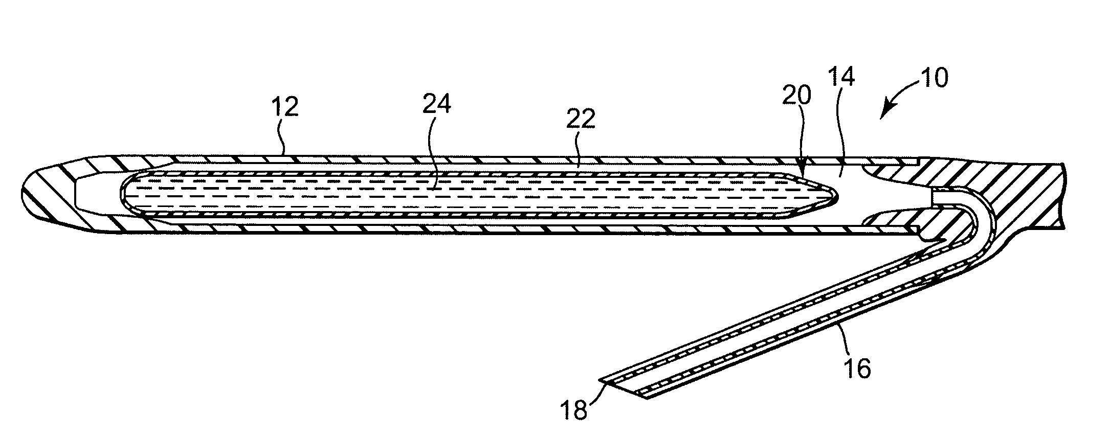
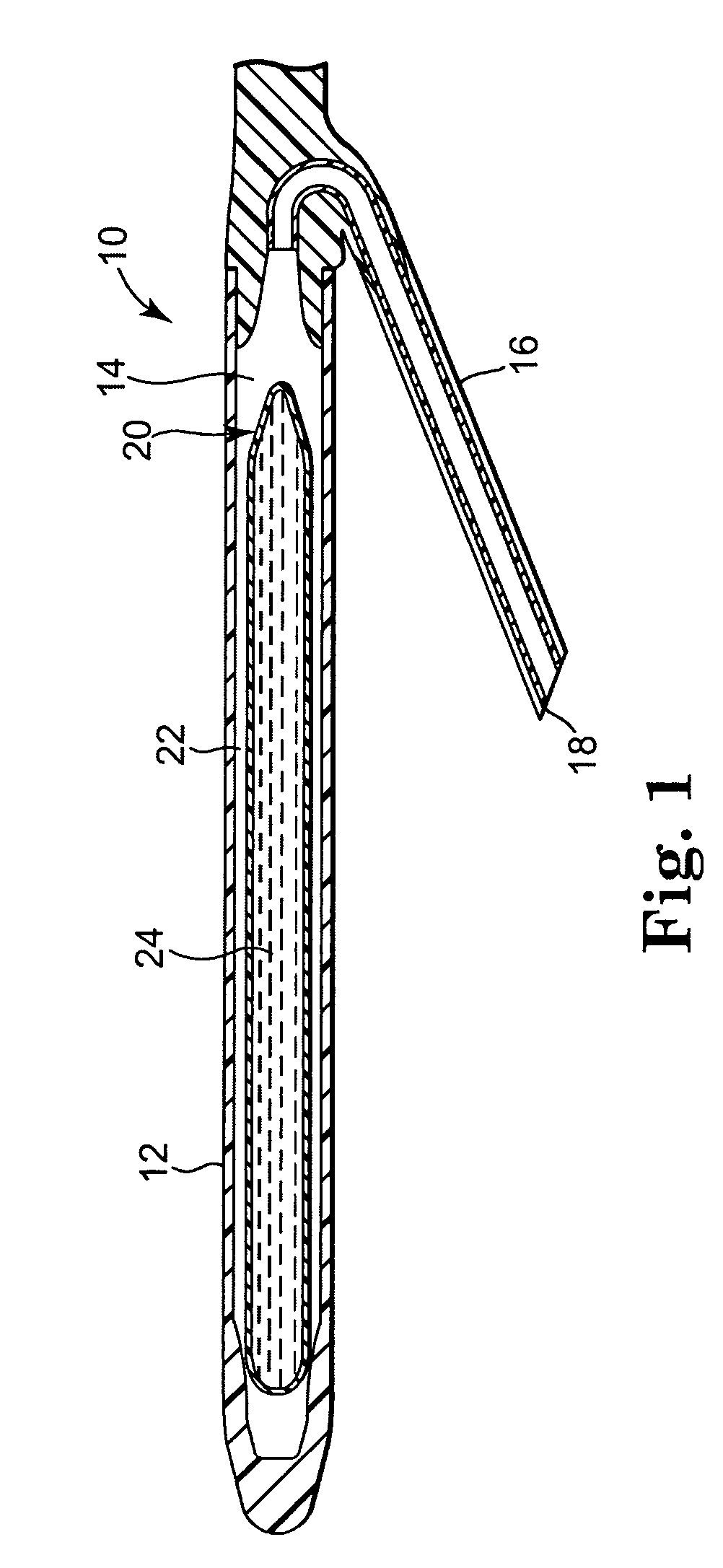
[0027]Referring now to the Figures, wherein the components are labeled with like numerals throughout the several Figures, and initially to FIG. 1, one exemplary configuration of an implantable and inflatable penile prosthesis device 10 is illustrated. In most cases, two of these devices 10 will be implanted into the corpus cavernosae of the penis. The device 10 generally includes an inflatable cylindrically shaped body portion 12 having an interior cavity 14 that extends along at least a portion of the length of the body portion 12. The device 10 further includes a tube 16 that extends from the body portion 12 and is used to transport an inflation fluid to and from the interior cavity 14. A distal end 18 of the tube 16 is in fluid communication with a pump assembly and supply reservoir (not shown) that provide a sufficient amount of fluid to inflate the body portion 12, as described in further detail below. The body portion 12 may be formed of a number of different materials that pr...


PUM


Abstract

A penile prosthesis is provided, which includes a generally cylindrical body portion comprising a cavity with an inner wall, a proximal end, a distal end, and at least one volume-displacing member occupying at least a portion of the cavity, wherein the at least one volume-displacing member is smaller in at least one dimension than the dimensions of the cavity to provide an internal chamber at least partially surrounding the at least one volume-displacing member and adjacent to the inner wall of the cavity. The prosthesis further includes a fluid transfer tube extending from the body portion for transferring fluid to and from the internal chamber, wherein the device is convertible from a flaccid condition to a rigid condition when a sufficient volume of fluid is transferred into the internal chamber to substantially fill the internal chamber.

Description

REFERENCE TO RELATED APPLICATIONS[0001]This application claims the benefit of U.S. Provisional applications having Ser. No. 60 / 476,844, filed Jun. 6, 2003, entitled “IMPROVEMENTS FOR TREATING ERECTILE DYSFUNCTION,” and Ser. No. 60 / 507,975, filed Oct. 2, 2003, entitled “INFLATABLE PENILE PROSTHESIS WITH VOLUME DISPLACEMENT MATERIALS AND DEVICES,” which applications are incorporated herein by reference in their entirety.TECHNICAL FIELD[0002]The present invention relates to systems for treating erectile dysfunction and other urological disorders. In particular, the invention relates to implantable penile prostheses.BACKGROUND OF THE INVENTION[0003]One common treatment for erectile dysfunction includes the use of a penile implant device. One type of penile implant device includes a pair of cylindrical prostheses that are implanted into the corpus cavernosae of the penis. In some instances, the prostheses are inflatable and are connected to a fluid-filled reservoir through a pump and val...

Claims


Application Information

Patent Timeline
Patent Type & Authority Patents(United States)
IPC IPC(8): A61F5/00A61F2/26
CPCA61F2/26
Inventor MISCHE, HANS A.
Owner BOSTON SCI SCIMED INC
Why Eureka
Try Eureka