Three-cone rock bit with multi-ported non-plugging center jet nozzle and method

a three-cone rock bit and center jet technology, applied in the field of oil field drilling equipment, can solve the problems of reducing the efficiency of drilling process, mud ball formation, and locking of rotary cutter cones, so as to reduce the damage to cutting surfaces, reduce the impact of mud ball, and reduce the effect of drilling process efficiency

Inactive Publication Date: 2003-06-24
DICKEY WINTON B
View PDF8 Cites 34 Cited by
  • Summary
  • Abstract
  • Description
  • Claims
  • Application Information

AI Technical Summary

Benefits of technology

The nozzle of the preferred embodiment contains a plurality of side passageways extending from the central passageway and through the nozzle sidewall. Such passageways of the nozzle are preferably positioned and adapted to produce a jetting of fluid (mud) toward the void of the drill bit and to produce a cross jetting of fluid through the void so that cuttings will not accumulate in the void, well bore, and on cutter cones. The cross jetting alleviates balling and plugging in the void. Side passageways in the nozzle typically have a constant diameter throughout their length defining cylindrical bores through the sidewall of the body. Alternately, side passageways may define an oval or slit shape throughout their length, thereby being adapted to create a fanning spray of drilling mud, thus lessening damage to cutting surfaces, which can be occasioned by high impact, tight jetting streams. Preferably, the shape of side passageways is constant throughout the entirety of side passageway length. To provide for side jetting, the side passageways extend through the nozzle sidewall at an angle perpendicular to the axis of the body or preferably at an angle of between ten and one-hundred-seventy degrees relative to the vertical axis. The range of angles allows the side passageways to direct fluid in an upward or downward direction as well as perpendicular to the axis of the drill bit. In the same preferred embodiment, side passageways are positioned on the body of the nozzle so that the inlet orifices of the side passageways are staggered in their placement on the central passageway. Staggering of inlet orifices along the central passageway is beneficial as it maintains the velocity of drilling mud through the central passageway. Side passageways draw on drilling mud flowing through the central passageway to produce side jetting. Thus, as drilling mud progresses through the nozzle, velocity of drilling mud moving through the central passageway will be inconsistent if inlet orifices leading to side passageways are randomly placed. However, properly spaced staggering of inlet orifices leading to side passageways along a descending taper shaped central passageway allows drilling mud to maintain substantially consistent velocity as drilling mud volume is channeled through side passageways selectively. Where staggered orifices are in place, velocity of drilling mud progressing through the nozzle has an opportunity to back up to its initial velocity before a subsequent inlet orifice draws on the volume of drilling mud within the central passageway. Consistent velocity within the central passageway is needed to maintain flow and to curtail small impediments in the drilling mud from plugging in the smaller inlet orifices leading to side passageways of the nozzle. This velocity will also cause temporarily obstructing particles and impediments in the drilling mud to be worn and washed away by fluid action, therefore reopening the small side passageways (side jets) in a short period. In this embodiment, the central passageway of the nozzle has a conical taper shape descending to the main exit aperture. This main exit aperture will be of sufficient size to avoid plugging, therefore permitting maintenance of central passageway velocity of drilling mud. The main exit aperture has a diameter of at least 8 / 32 inches. Preferably, the main exit aperture has a diameter in a range of 8 / 32 to 20 / 32 inches. A descending tapering shape of the central passageway additionally maintains velocity of drilling mud within the central passageway, despite the existence of a plurality of staggered side passageways directing flow of the drilling mud in various directions. Functionally applying the above described apparatus provides a method of reducing mud accumulation in the dome of the rock bit and on cutter cones, thereby, improving the effectiveness of the center jet nozzle.
A second embodiment of the center jet nozzle has the same limitations of the first nozzle, however, the central passageway of the nozzle defines a sectional descending shape. The sectional descending passageway maintains fluid velocity within the nozzle central passageway, as does the tapered passageway defined by the first embodiment, however, further providing a sectional contoured shape that facilitates movement of drilling fluid and which further resists clogging of side passageways by kicking small impediments toward the center of the cavity. Volume of fluid passing through this central passageway decreases with the shape of the passageway, consequently, fluid velocity is maintained in the central passageway, despite the presence of a plurality of staggered side passageways which draw on fluid (drilling mud) flowing through the central passageway.
The first and second embodiments of the present invention are optimally realized by propelling drilling mud through the central passageways at velocities causing minimal damage to nozzle components and which are most likely to avoid clogging of side passageways. Accordingly, the present invention provides for methods of using the rotary drill bit and contained non-clogging nozzles wherein drilling mud within the central passageway is optimally propelled at a velocity in the range of 75 to 300 feet per second as measured within the nozzle central passageway.

Problems solved by technology

Drilling mud and formation cuttings often accumulate within the void between and above cutting surfaces, thereby forming a mud ball that becomes impacted.
Balling reduces the efficiency of the drilling process because a portion of the bit known as the dome (area above cutter cones) is packed off, causing the rotary cutter cones to become locked.
This causes rotary cutter cones to skid on the bottom of the hole, therefore, slowing the rate of penetration.
The design dilemma with such smaller holes in multi-ported center jet nozzles is that they cannot be run in a normal drilling operation because of the risk of their becoming plugged with impediments typically present in drilling mud.
When plugging of these smaller holes in the central nozzle occurs, the usefulness of the center jet is compromised.

Method used


Image

  • Three-cone rock bit with multi-ported non-plugging center jet nozzle and method
  • Three-cone rock bit with multi-ported non-plugging center jet nozzle and method
  • Three-cone rock bit with multi-ported non-plugging center jet nozzle and method

Examples


Embodiment Construction

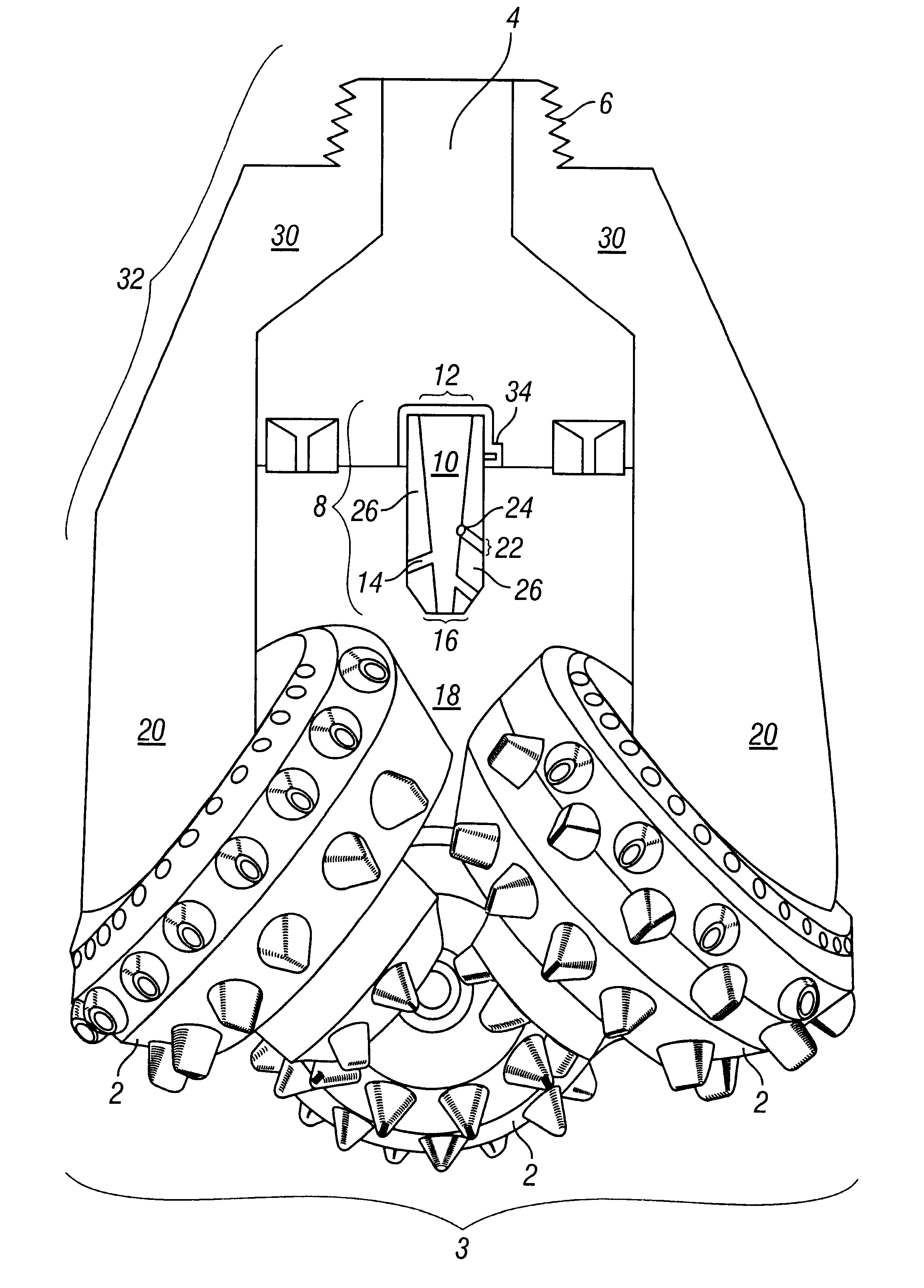
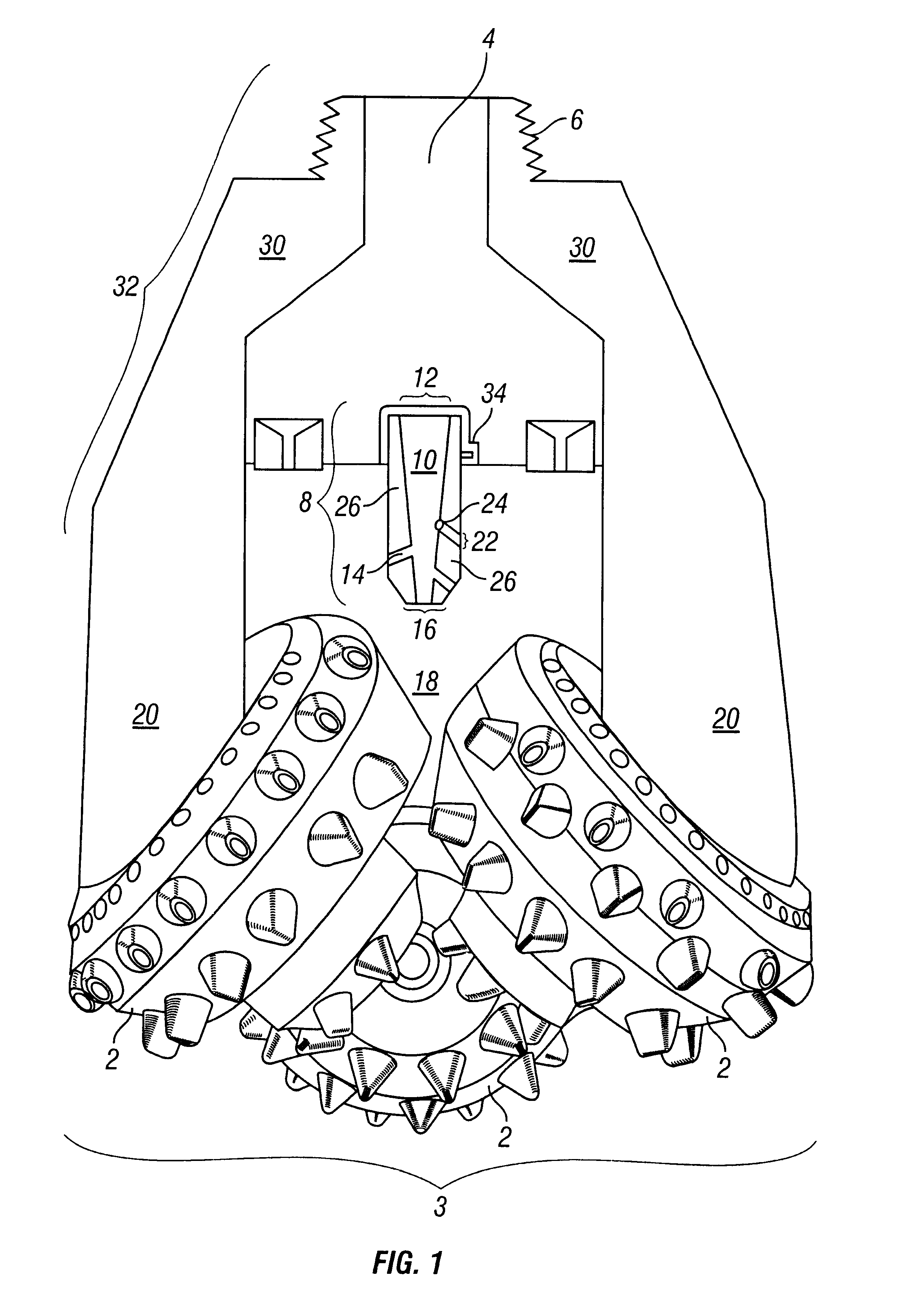
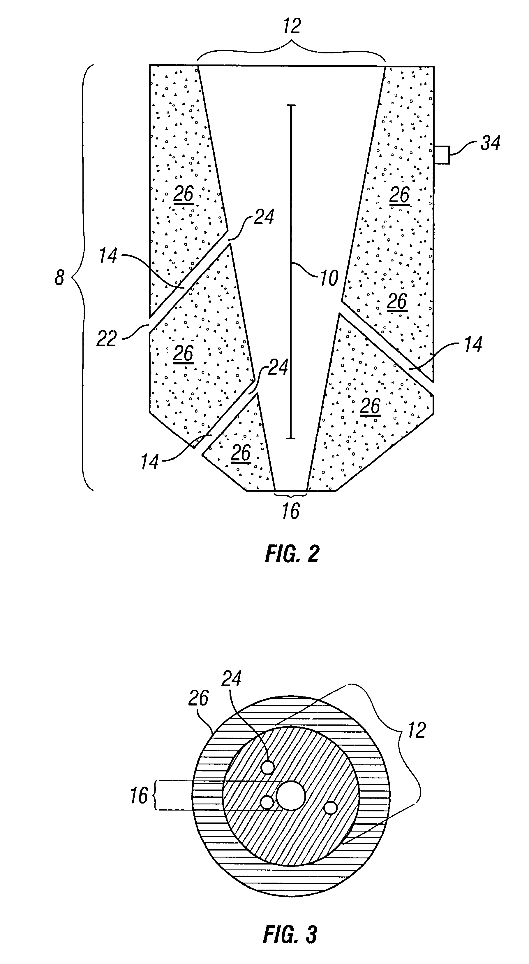
The present invention generally provides a non-plugging center jet nozzle 8 and a self-cleaning drill bit, particularly a three-cone rotary drill bit 32, incorporating a nozzle 8. In general, the nozzle 8 has an inlet aperture 12, a main exit aperture 16, and a plurality of side passageways 14. Preferably, the inlet aperture 12 on the nozzle 8 has a greater cross-sectional area than the sum of the cross-sectional areas of the main exit aperture 16 and all exit orifices 22 on the nozzle 8. The exit aperture 16 is of sufficient size (preferably at least 8 / 32 inch diameter) so as not to be plugged by any impediments in drilling mud. Preferably, the main exit aperture has a diameter in a range of 8 / 32 to 20 / 32 inches. So long as the exit aperture 16 remains unplugged, then smaller inlet orifices 24 to side passageways 14 will avoid permanent clogging. The side passageways 14 intersect the central passageway 10. Typically, the side passageways 14 intersect the central passageway 10 at sh...


PUM


Abstract

A three-cone rock bit employing a non-plugging center jet nozzle with a plurality of staggered inlet orifices leading to side passageways to reduce bit balling. The nozzle defines a tapered cavity through which drilling mud flows and exits in streams. Streams are directed from the nozzle through a main exit aperture of sufficient size to avoid plugging and from side passageways boring through a sidewall of the nozzle. Jetting streams promote washing of voids within the bit and of cutting surfaces. The nozzle uses staggered inlet orifices leading to side passageways, in conjunction with a tapering shape of a central passageway to facilitate maintenance of drilling mud velocity within the central passageway and thus of stream velocity to targeted regions of the drill bit.

Description

CROSS-REFERENCE TO RELATED APPLICATIONSNot applicable.STATEMENT REGARDING FEDERALLY SPONSORED RESEARCH OR DEVELOPMENTNot applicable.BACKGROUND OF THE INVENTION1. Field of InventionThe present invention relates to the field of oil field drilling equipment. More specifically, the invention relates to a three-cone rock bit using a non-plugging center jet nozzle with a plurality of side passageways that are situated in a staggered fashion to prevent balling, or packing of the drill bit.2. Related ArtIn the drilling of oil wells, drilling fluid, or mud, provides lubrication, cooling, and cleaning by high pressure jets for the drill bit and provides for removal of the cuttings from the well bore. The mud circulates down through a drill string, into the drill bit body, typically through three nozzles positioned within the drill bit, and toward the bottom of the well bore. Nozzles are particularly useful because the relatively high-pressure mud creates high velocity jet streams within the h...

Claims


Application Information

Patent Timeline
Patent Type & Authority Patents(United States)
IPC IPC(8): E21B10/18E21B10/08
CPCE21B10/18
Inventor DICKEY, WINTON B.
Owner DICKEY WINTON B
Why Eureka
Try Eureka