Carpenter's pitch square

a carpenter's pitch and square technology, applied in the field of measuring tools, can solve the problems of difficult to determine straight lines at long distances, difficult to be in a position to view the markings on the square, and not always easy to use such squares to generate straight lines, etc., to achieve accurate and simpler way of scribe, widen the area that can be scribe, and achieve the effect of much more efficient scrib

Inactive Publication Date: 2008-07-15
MORRELL MICHAEL F
View PDF24 Cites 45 Cited by
  • Summary
  • Abstract
  • Description
  • Claims
  • Application Information

AI Technical Summary

Benefits of technology

[0012]The lockable pin transforms the square into a fully adjustable square that now has versatility that enables a user to perform tasks that could not be done before with such ease. The lockable pin transforms the square into a fixed jig in order to do multiple and repetitive markings with not only speed, but repetitive accuracy that does not exist with conventional squares. The lockable pin allows the user to use the square in positions that are non-surface oriented (i.e., the square is able to perform squaring positions that are non-pivot oriented as well as pivot oriented). The lockable pin allows the user to scribe much more efficiently and widens the area that can be scribe in addition to delivering a much more accurate and simpler way to scribe. The recess in the bar allows the user to slide the pin into the recess so that the square can be used in the pivot positions at all times and allows the user the option of the pin when needed and use of the square as a conventional square when the pin is not needed. The lockable pin also allows the user to copy any existing angle as a template once the pin is in a locked position and then transfer the angle onto another location without reliance on human memory or pivot markings.

Problems solved by technology

It is not always easy to use such squares to generate straight lines, especially in cramped areas where it is difficult to be in a position to view the markings on the square in order to orient the square in a desired manner.
It is also difficult to determining straight lines at long distances, up heights such as on roofs or ceilings, across spaces where there are encumbrances or across areas having depths which cannot be traversed (such as roofs only having the end rafters in place).
However, the layout bar needs to be mechanically connected to the square which can result in misalignment and requires multiple adjustment points in order to obtain a desired angle.
However, the laser square can not be locked into a specific orientation and requires visual access to each location at which the square is positioned in order to determine the proper orientation of the square.

Method used


Image

  • Carpenter's pitch square
  • Carpenter's pitch square
  • Carpenter's pitch square

Examples


Embodiment Construction

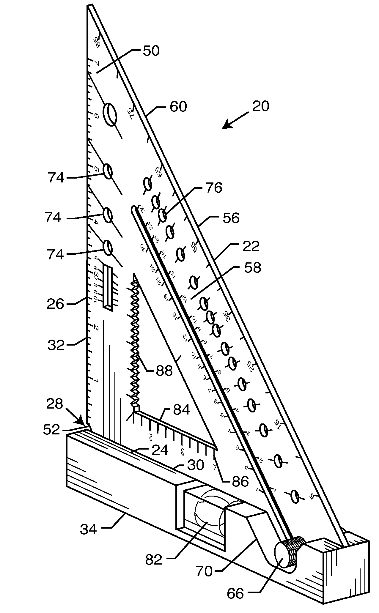
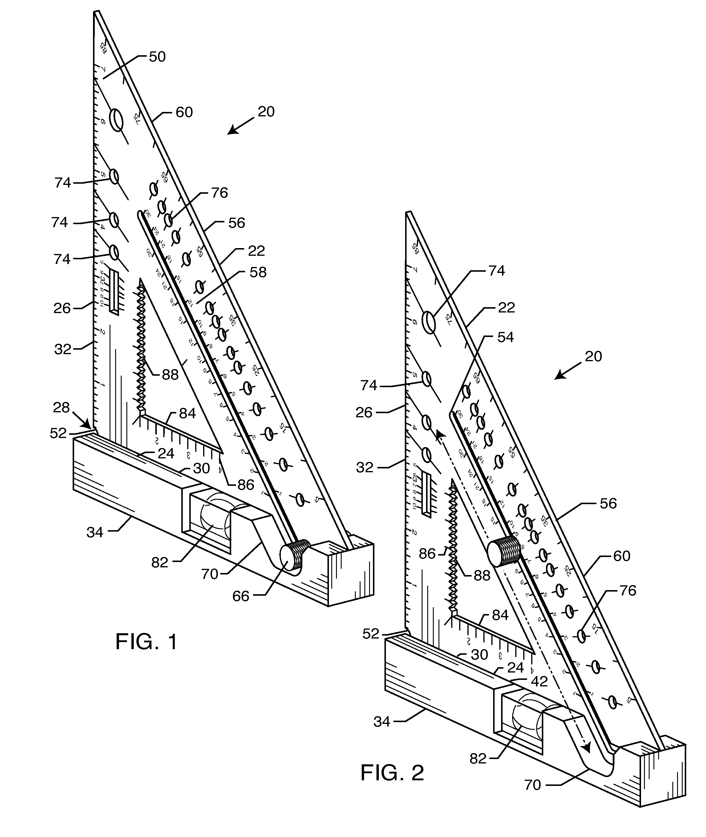
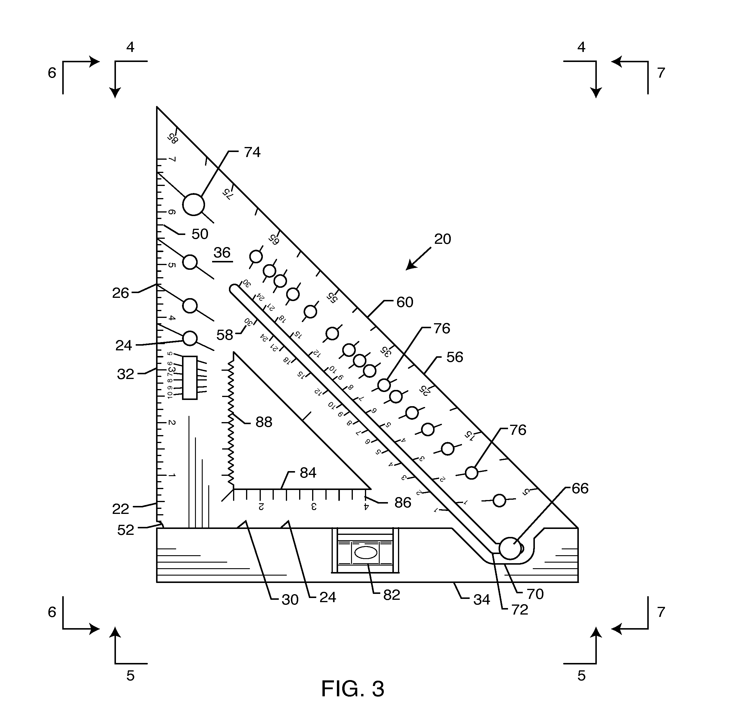
[0031]As shown in the figures for purposes of illustration, the present invention is concerned with a square 20, 90 for use in carpentry, plumbing, electrical work or the like. The present invention provides a number of improvements that include accurately scribing sets into locked pitch and angle positions. The square can now be placed on work that is not a surface, mark level cuts on rafters, and mark multiple angles without pivot. The square is now adjustable. The square includes features such as a pencil sharpener, a magnet for steel framing. The square can be used as a saw guide in an angle position.

[0032]In an embodiment of the invention, the square 20 (FIGS. 1-13) includes a triangular base 22 having first and second straight sides 24, 26 joined to form a right angle at a corner 28. The first and second sides 24, 26 define straight edges 30, 32 of the base 22.

[0033]The square 20 includes a bar 34 connected to the base 22 along the first side 24. The bar 34 extends perpendicul...


PUM


Abstract

A carpenter's square includes a triangular base having first and second sides joined to form a right angle. A first elongated slot is disposed within the base parallel to a third side thereof; and a pin is selectively positionable along the length of the slot. The pin provides a mechanism for fixing the base in a specific orientation relative to an edge of an object when the pin is in a locked position within the slot.

Description

BACKGROUND OF THE INVENTION[0001]The present invention relates generally to measuring tools. More particularly, the present invention relates to a square having a mechanism for fixing the square in a particular orientation.[0002]Carpenter's squares, sometimes referred to as SPEED squares, framing squares, rafter squares, rafter angle squares and the like, are used for a variety of tasks by carpenters, electricians, plumbers and other similar craftsmen. These squares typically have a main body with three sides, two of which meet at a right angle. The sides are straight edges marked with rulers and lay out lines. The rulers are used to mark out rafter layouts straight line cuts, angle line cuts, etc. Such squares are used for erecting roofs, in which common rafters, hip rafters, valley or jack rafters, and cornices are cut with the proper plumb, heel and side cuts so that the rafters can be put in place with the proper pitch and length.[0003]More particularly, these squares are used f...

Claims


Application Information

Patent Timeline
Patent Type & Authority Patents(United States)
IPC IPC(8): B43L7/027
CPCB25H7/00B43L7/0275G01B3/566B43L13/002B43L23/08B43L12/02
Inventor MORRELL, MICHAEL F.
Owner MORRELL MICHAEL F
Why Eureka
Try Eureka