Mounting structure of curtain airbag in vehicle
a technology of mounting structure and curtain airbag, which is applied in the direction of vehicle components, superstructure subunits, roofs, etc., can solve the problems of insufficient formation of inflation passage between a-pillar and pillar trim, and the configuration is difficult to supply a sufficient expansion force of curtain airbag, so as to achieve smooth deployment
- Summary
- Abstract
- Description
- Claims
- Application Information
AI Technical Summary
Benefits of technology
Problems solved by technology
Method used
Image

Examples
first embodiment
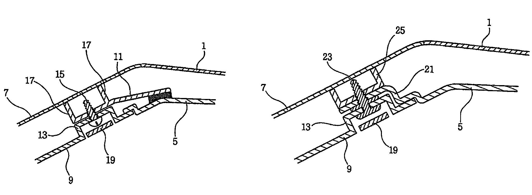
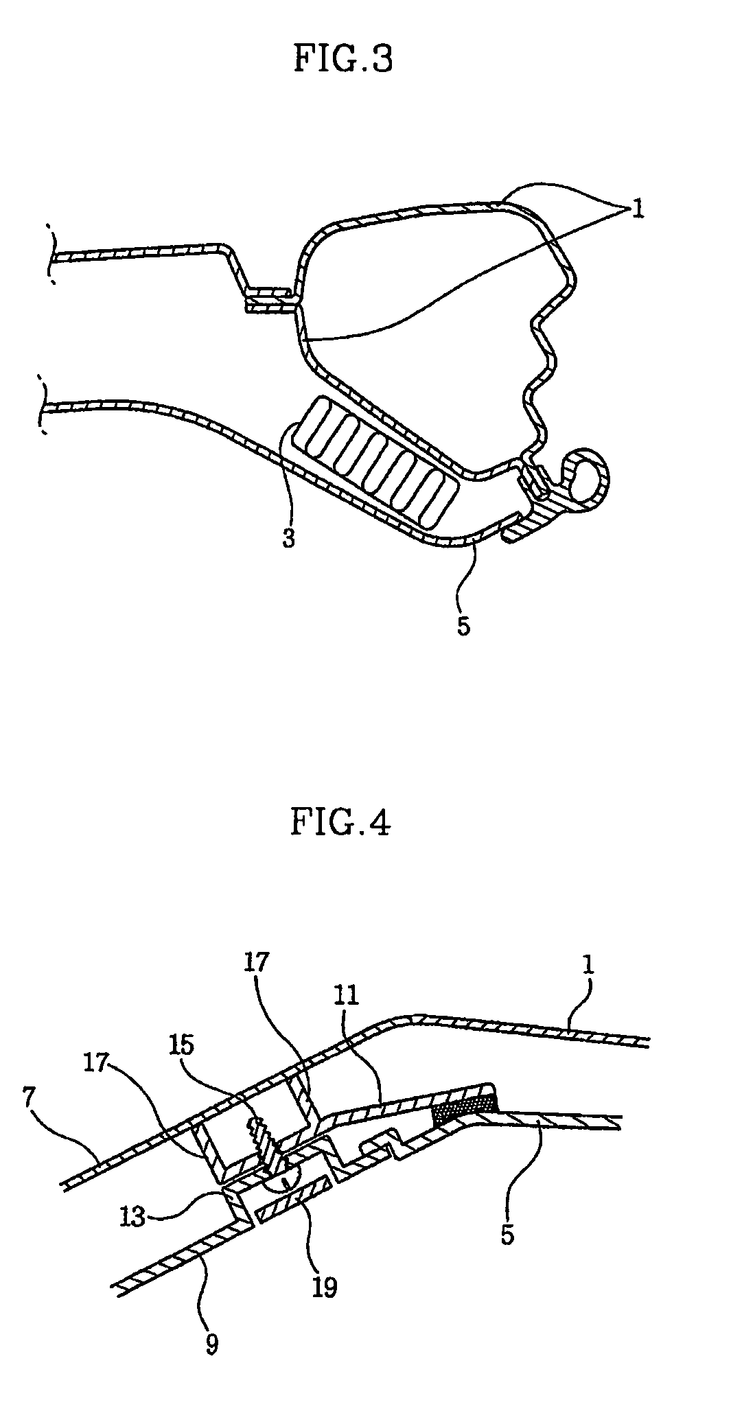
[0017]As illustrated in FIG. 4, the force transmission means according to the present invention includes an extension plate 11 that contacts at one end thereof with the inner surface of head liner 5 while the other end extends to the interior of pillar trim 9. A coupling means couples pillar trim 9 to extension plate 11.
[0018]The coupling means is constituted by a boss 13 inwardly protruding at pillar trim 9. A coupling screw 15 penetrates from boss 13 to extension plate 11. A supporter 17 is integrally formed with extension plate 11 for maintaining the end of coupling screw 15 at a distance from pillar 7 and for locating pillar trim 9 apart from pillar 7. A cover 19 conceals boss 13.
[0019]Accordingly, coupling screw 15 that couples pillar trim 9 to extension plate 11 is invisible in the passenger compartment via cover 19.
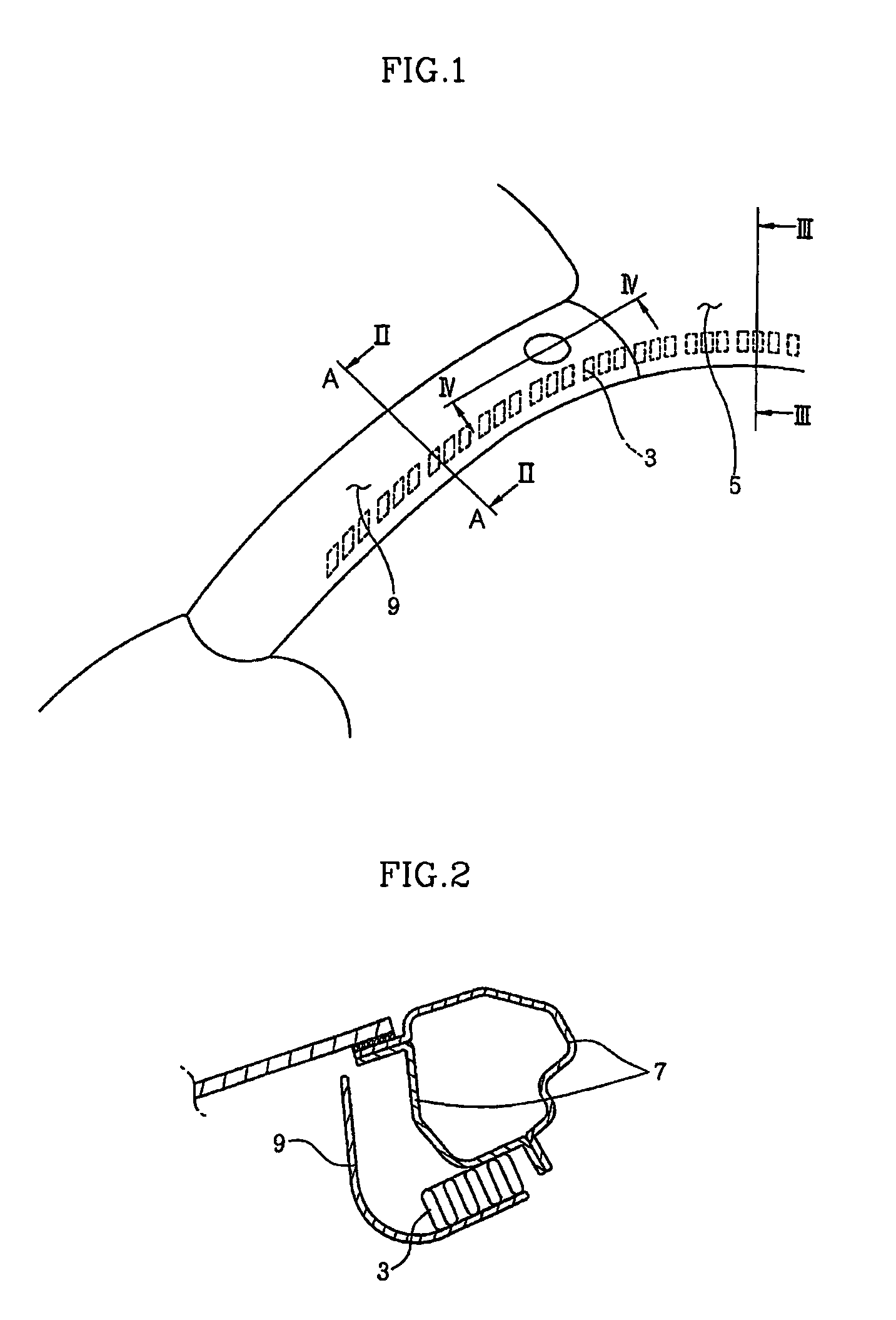
[0020]Under such construction, if curtain airbag 3 pushes head liner 5 during the deployment, and the thrust force of curtain airbag 3 is transmitted to pillar tri...
second embodiment
[0022]Referring now to FIG. 5, the force transmission means according to the present invention is composed of a liner extension 21 and coupling means. Liner extension 21 integrally extends from one end (adjacent to pillar trim 9) of head liner 5 to the interior of pillar trim 9, and the coupling means couples pillar trim 9 to liner extension 21.
[0023]In comparison with the first embodiment, liner extension 21 is integrally formed with head liner 5 for transmitting the force of head liner 5 to pillar trim 9 without the aid of a separate extension plate.
[0024]The coupling means includes boss 13 protruding inward at pillar trim 9. A fastener 23 is rotatably installed in relation to boss 13 and screws to liner extension 21. A supporter 25 is fixed to liner extension 21 for maintaining the end of fastener 23 at a distance from pillar 7 and for placing pillar trim 9 apart from pillar 7. Cover 19 conceals boss 13.
[0025]Supporter 25 contacts or welds in advance with liner extension 21, wher...
third embodiment
[0027]As illustrated in FIG. 6, the force transmission means according to the present invention includes an elastic plate 27 that is fixed at one surface thereof to an inner side of head liner 5 while the other surface closely attaches to an inner side of pillar trim 9.
[0028]Elastic plate 27 is composed of a flat planar portion 29 fixed in head liner 5, and an arc sectional portion 31 extending from flat planar portion 29 and closely attaches to the interior of pillar trim 9 by bypassing the contiguous region of head liner 5 and pillar trim 9.
[0029]Arc sectional portion 31 of elastic plate 27 transmits the force of head liner 5 to pillar trim 9 in the course of the deployment of curtain airbag 3.
[0030]In the third embodiment, once a space is formed between pillar trim 9 and pillar 7 for the inflation of the curtain airbag, a separate tether or the like is preferably added for preventing a complete detachment of pillar trim 9 from pillar 7.
[0031]As apparent from the foregoing, there ...
PUM
 Abstract
Description
Claims
Application Information
 - R&D Engineer
- R&D Manager
- IP Professional
- Industry Leading Data Capabilities
- Powerful AI technology
- Patent DNA Extraction
Browse by: Latest US Patents, China's latest patents, Technical Efficacy Thesaurus, Application Domain, Technology Topic.
© 2024 PatSnap. All rights reserved.Legal|Privacy policy|Modern Slavery Act Transparency Statement|Sitemap