Eureka AIR delivers breakthrough ideas for toughest innovation challenges, trusted by R&D personnel around the world.

Wireless system for one or more electrical switching apparatus

a technology of electrical switching apparatus and wireless system, which is applied in the field of communication systems, can solve the problems of compromising the insulation system, affecting the efficiency of the insulation system, and affecting the efficiency of the insulation system, and achieves the effect of low power

Active Publication Date: 2008-08-26
EATON INTELLIGENT POWER LTD
View PDF19 Cites 23 Cited by
  • Summary
  • Abstract
  • Description
  • Claims
  • Application Information

AI Technical Summary

Problems solved by technology

For example, every time a circuit breaker or contactor interrupts a current, a certain amount of contact wear and erosion occurs.
As the contact condition degrades, the contact resistance can result in a higher than normal contact temperature, which can compromise the insulation system.
A higher than normal apparatus-to-bus bar or cable termination resistance can also result in an over-temperature insulation condition.
As the contacts wear, this travel will increase.
Breaker contact wear can also contribute to the termination temperature rise.

Method used


Image

  • Wireless system for one or more electrical switching apparatus
  • Wireless system for one or more electrical switching apparatus
  • Wireless system for one or more electrical switching apparatus

Examples


example 1

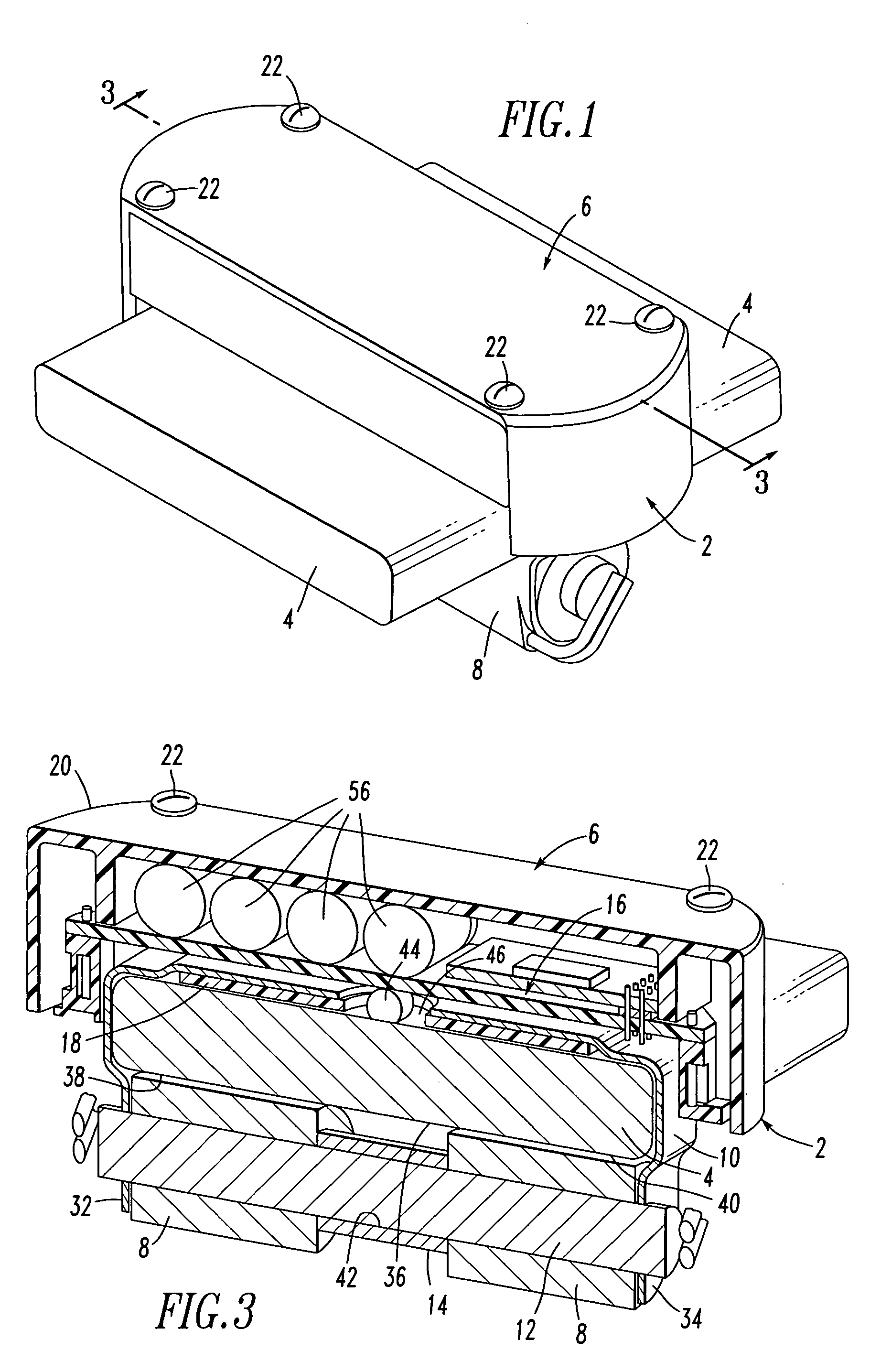
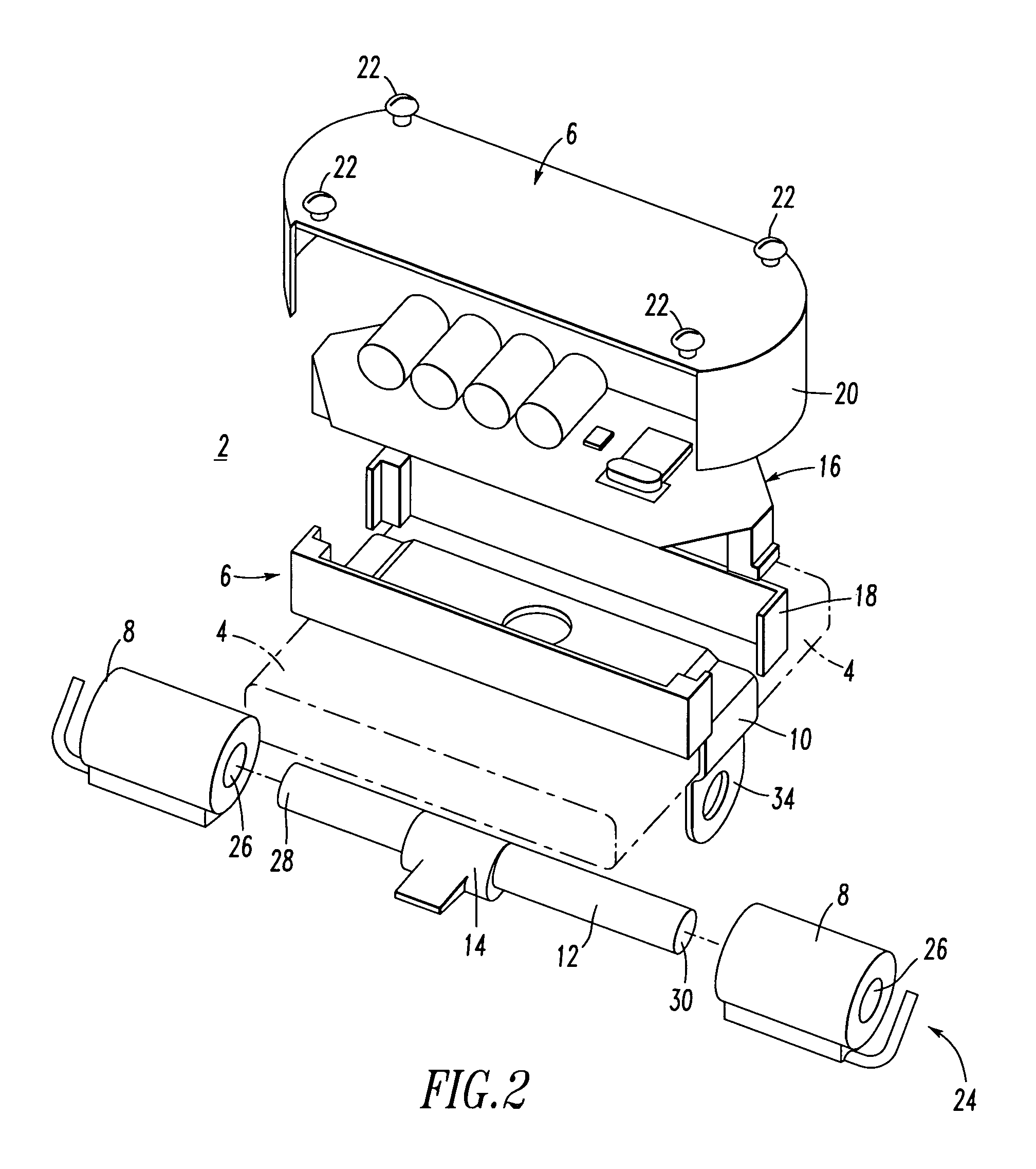
[0058]The design of the sensor device 2 fits a power bus bar 4 with suitable cross sectional dimensions (e.g., without limitation, about 3.0 inches×about 0.5 inches), although a wide range of other power bus dimensions may be employed by employing suitable sizes of the flux concentrator member 10, the ferrite core 12 and the spacer 14.

example 2

[0059]A wide range of temperature sensors may be employed. For example, a silicon diode (not shown) may be suitably thermally coupled with or suitably disposed proximate to the surface 46 of the power bus bar 4 for heating thereby. For example, the forward voltage drop across the diode decreases linearly with an increase in the temperature of the power bus bar 4. The forward voltage of the diode as energized by the power supply 24 is electrically input by an electronics board assembly, such as 16.

[0060]Although a silicon diode is disclosed, other forward biased PN junctions could be used, such as, for example, gallium arsenide. Alternatively, any suitable active or passive temperature measuring or sensing device (e.g., RTDs (resistive temperature detectors), various metals (e.g., copper, nickel, platinum) having resistance, voltage or current characteristics versus temperature) may be employed.

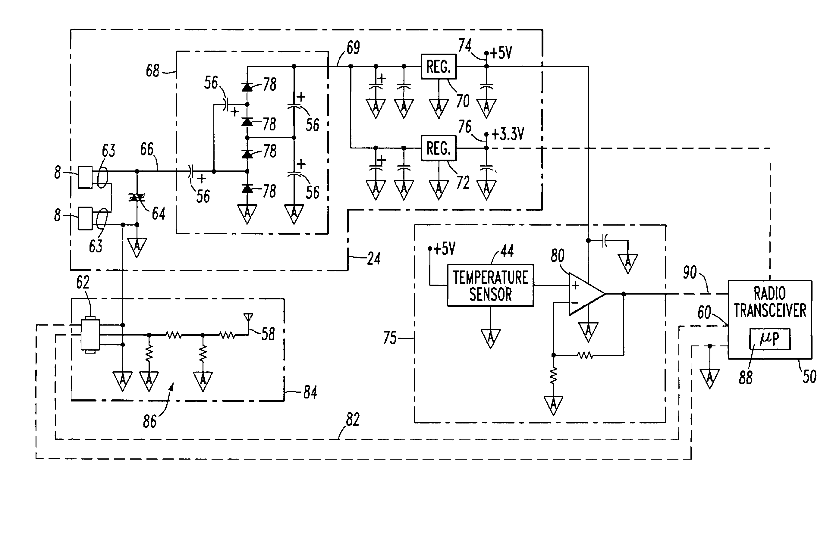
[0061]Referring to FIG. 4, the electronics board assembly 16 is shown. The assembly 16 inc...

example 3

[0063]The antenna 58 may be a printed circuit board inverted-L antenna with Gamma match. For example, the length of the antenna 58 may be designed for a quarter wave 915 MHz signal.


PUM


Abstract

A system displays information from and controls electrical switching apparatus, such as circuit breakers. The system includes a plurality of circuit breakers having separable contacts and a plurality of conditions, such as bus temperature and contact wear. A plurality of sensors are structured to sense the conditions of the circuit breakers and to communicate the sensed conditions over corresponding wireless signals. A display and control unit is operatively associated with the circuit breakers and is structured to receive the corresponding wireless signals and display information corresponding to the sensed conditions or to control the circuit breakers based upon one or more of the sensed conditions.

Description

[0001]This application is a continuation-in-part of application Ser. No. 11 / 038,899, filed Jan. 19, 2005 now U.S. Pat. No. 7,253,602, and entitled “Self-Powered Power Bus Sensor Employing Wireless Communication,” which is a continuation-in-part of application Ser. No. 10 / 962,682, filed Oct. 12, 2004 now U.S. Pat. No. 7,145,322, and entitled “Self-Powered Power Bus Sensor Employing Wireless Communication”.BACKGROUND OF THE INVENTION[0002]1. Field of the Invention[0003]This invention pertains generally to communication systems and, more particularly, to such systems providing communications to or from one or more electrical switching apparatus, such as circuit breakers.[0004]2. Background Information[0005]An electrical distribution system typically consists of a plurality of protective, metering and control devices mounted within an enclosure, such as a switchgear or motor control center metal cabinet or suitable plastic enclosure. A wired communication mechanism is often provided tha...

Claims


Application Information

Patent Timeline
Patent Type & Authority Patents(United States)
IPC IPC(8): G08B21/00
CPCG01D21/00G01K13/00H01H1/0015H02H1/063H02H5/04H02H7/22H02H1/0061G01K2215/00H01H2071/006H01H2300/03Y04S20/227Y02B90/224Y04S20/14Y02B70/3241H01H2011/0068Y02B90/20Y02B70/30Y04S20/20
Inventor BENKE, JAMES J.ENGEL, JOSEPH C.LAGREE, JAMES L.LUEBKE, CHARLES J.SOLVESON, MARK G.
Owner EATON INTELLIGENT POWER LTD
Why Eureka
Eureka Blog
Learn More