Connectors and contacts for transmitting electrical power

a technology of electrical power transmission and connectors, applied in the direction of coupling device details, coupling contact members, coupling device connections, etc., can solve the problems of erroneous installation of power contacts configured for header connectors, increased assembly costs, and potential human error in production and assembly processes

Active Publication Date: 2008-09-16
FCI AMERICAS TECH LLC
View PDF267 Cites 72 Cited by
  • Summary
  • Abstract
  • Description
  • Claims
  • Application Information

AI Technical Summary

Problems solved by technology

Assembly costs can also be driven higher by the use of two different types of power contacts, as different processes and machinery may be required to assemble the two types of power contacts.
Also, the use of two different types of power contacts can introduce the potential for human error in the production and assembly processes.
For example, a power contact configured for the header connector may be erroneously installed in the receptacle connector when different types of power contacts are used in the header and receptacle connectors.

Method used


Image

  • Connectors and contacts for transmitting electrical power
  • Connectors and contacts for transmitting electrical power
  • Connectors and contacts for transmitting electrical power

Examples


Embodiment Construction

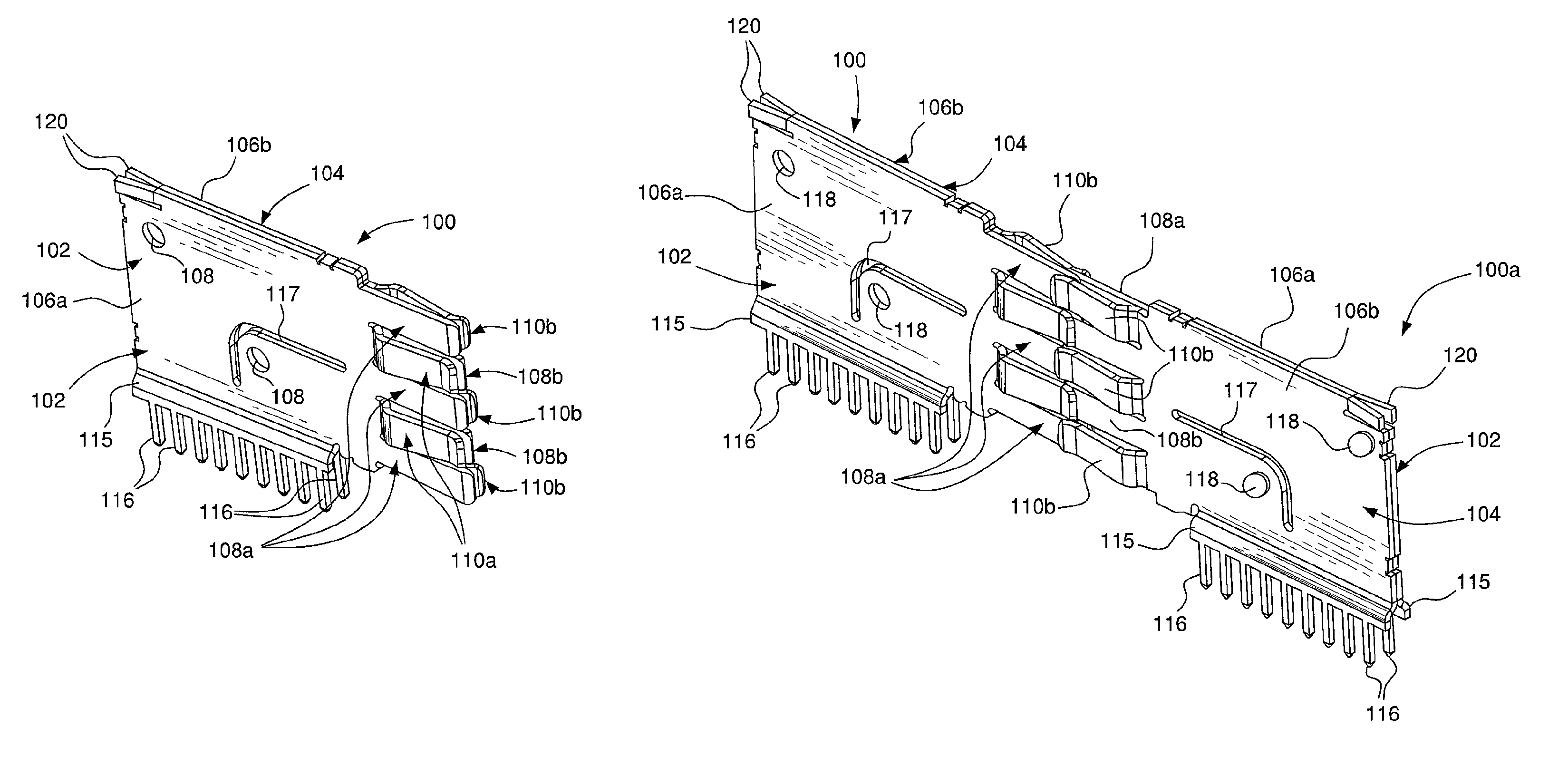
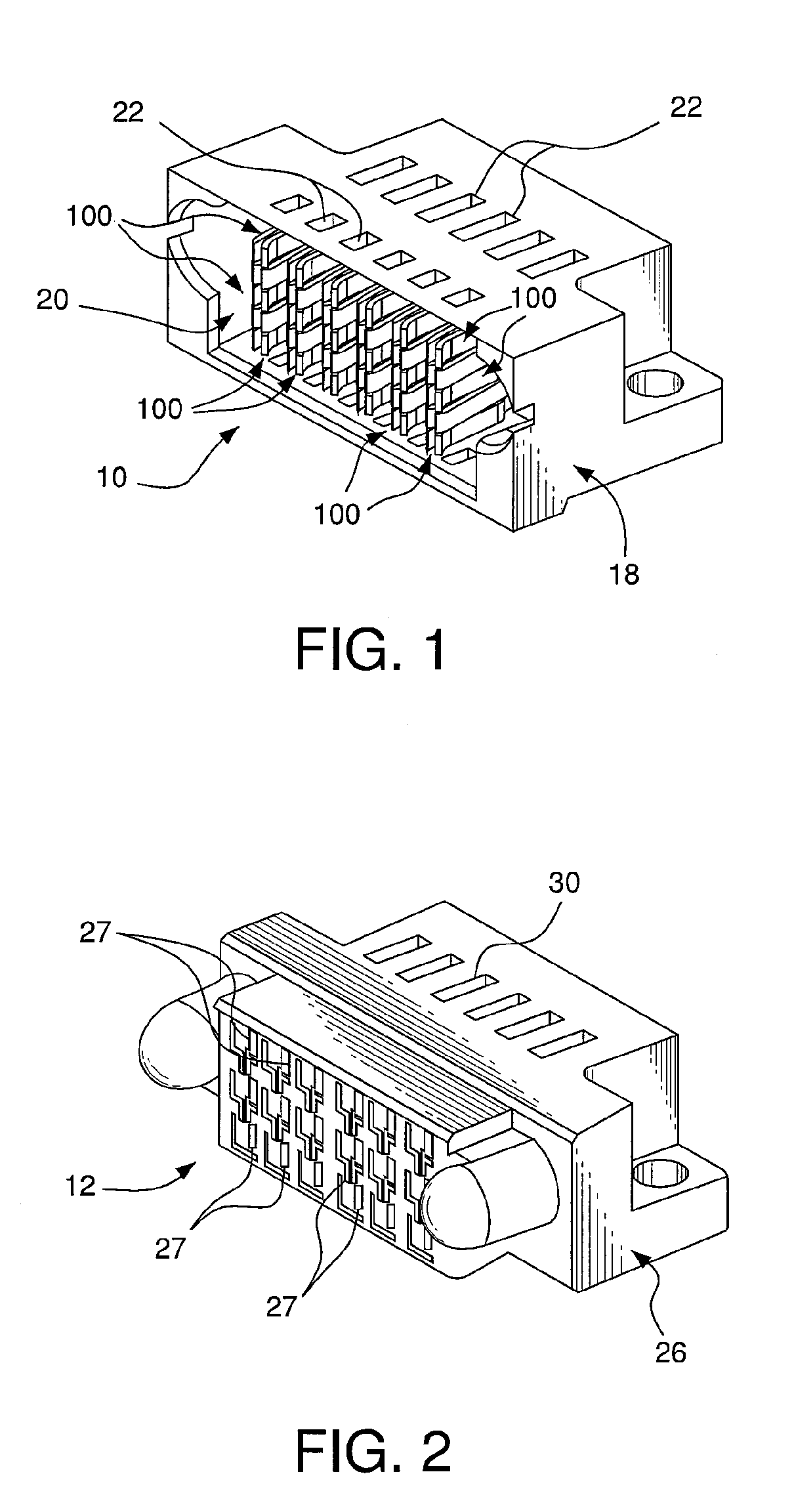
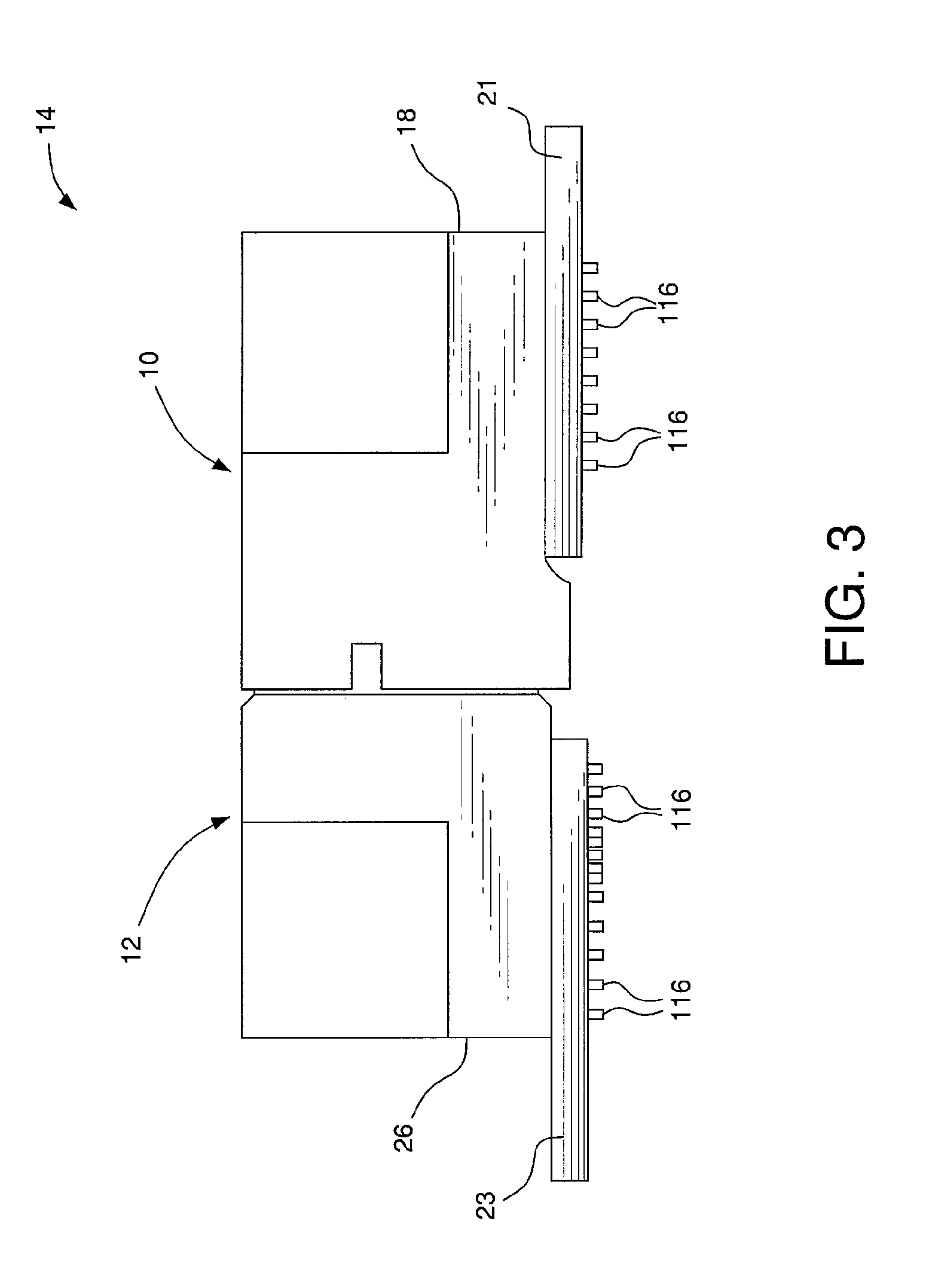
[0034]FIGS. 1 and 3 depict a preferred embodiment of a header connector 10. The header connector 10 comprises a plurality of power contacts 100. FIGS. 2 and 3 depict a preferred embodiment of a receptacle connector 12 that mates with the header connector 10. The receptacle connector 12 comprises a plurality of power contacts that are identical to, and mate with the power contacts 100 of the header connector 10. For clarity of illustration, the power contacts of the receptacle connector 12 are denoted by the reference character 100a in the figures. The header connector 10 and the receptacle connector 12 form a connector system 14.

[0035]The header connector 10 is depicted with six of the power contacts 100 for exemplary purposes only. Alternative embodiments of the header connector 10 can include more, or less than six of the power contacts 100. For example, alternative embodiments can include only one of the power contacts 100.

[0036]The header connector 10 can be mounted on a substra...


PUM


Abstract

A connector system includes a first connector, and a second connector that mates with the first connector. The same type of power contact is used in the first and second connectors.

Description

CROSS REFERENCE TO RELATED APPLICATIONS[0001]This application is related to U.S. application Ser. No. 11 / 019,777, filed Dec. 21, 2004; and U.S. application Ser. No. 11 / 408,437, filed Apr. 21, 2006. The contents of each of these applications is incorporated by reference herein in its entirety.FIELD OF THE INVENTION[0002]The present invention relates to electrical connectors, and contacts used therein, that are configured to transmit electrical power.BACKGROUND OF THE INVENTION[0003]Connector systems for transmitting electrical power typically comprise a header connector, and a receptacle connector that mates with and receives a portion of the header connector. The header connector can include one or more power contacts that engage complementary one or more power contacts on the receptacle connector, to establish electrical and mechanical contact between the header and receptacle connectors.[0004]The power contacts used in the header connector are usually configured differently than t...

Claims


Application Information

Patent Timeline
Patent Type & Authority Patents(United States)
IPC IPC(8): H01R25/00
CPCH01R12/7088H01R13/28
Inventor NGO, HUNG VIET
Owner FCI AMERICAS TECH LLC
Why Eureka
Try Eureka