Zoom lens system

Active Publication Date: 2008-10-14
LARGAN PRECISION
View PDF2 Cites 10 Cited by
  • Summary
  • Abstract
  • Description
  • Claims
  • Application Information

AI Technical Summary

Benefits of technology

[0021]The focal length of the negative meniscus lens element of the second lens group is f2, and the focal length of the negative meniscus lens element of the second lens group is f3, the focal length of the positive meniscus lens element of the fourth lens group is f7, the focal length of the zoom lens system in wide mode is fw, and they satisfy the following relations: 1.0<|f2|/fw<2.6—(5), 2.0<f3/fw<4.2—(6), 1.0<f7/fw<2.5—(7). In the above relations 5, 6 and 7, if the parameter is smaller than the above low limit, the refractive power of the lens elements will be too great, and if the lens elements are made of plastic, the temperature characteristic will not be good, and the eccentric-caused manufacturi

Problems solved by technology

After further study, we found that the above conventional lens systems still have the following problems:
When in use, the lens element protrudes outward, which leads to the problem of waterproof and falling off.
Therefore, it will be a problem if th

Method used


Image

  • Zoom lens system
  • Zoom lens system
  • Zoom lens system

Examples


Example

[0038]The first embodiment related description:

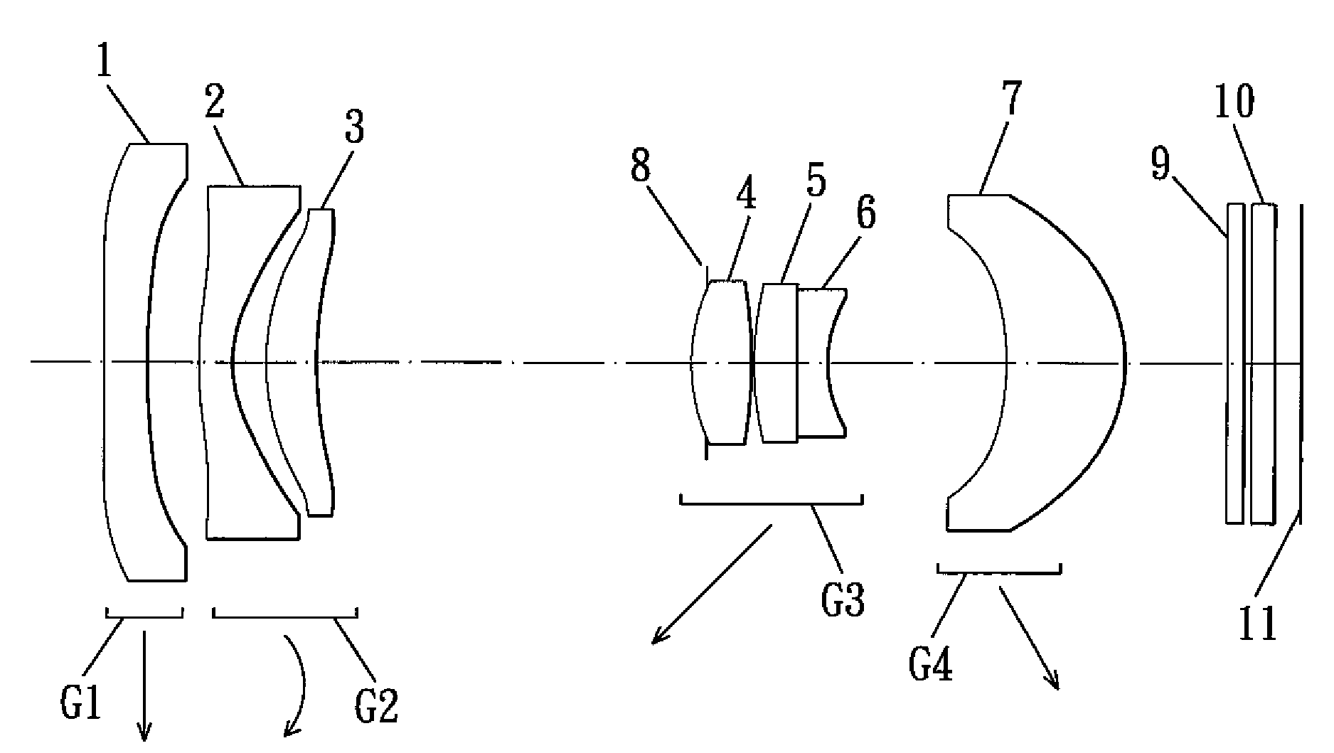
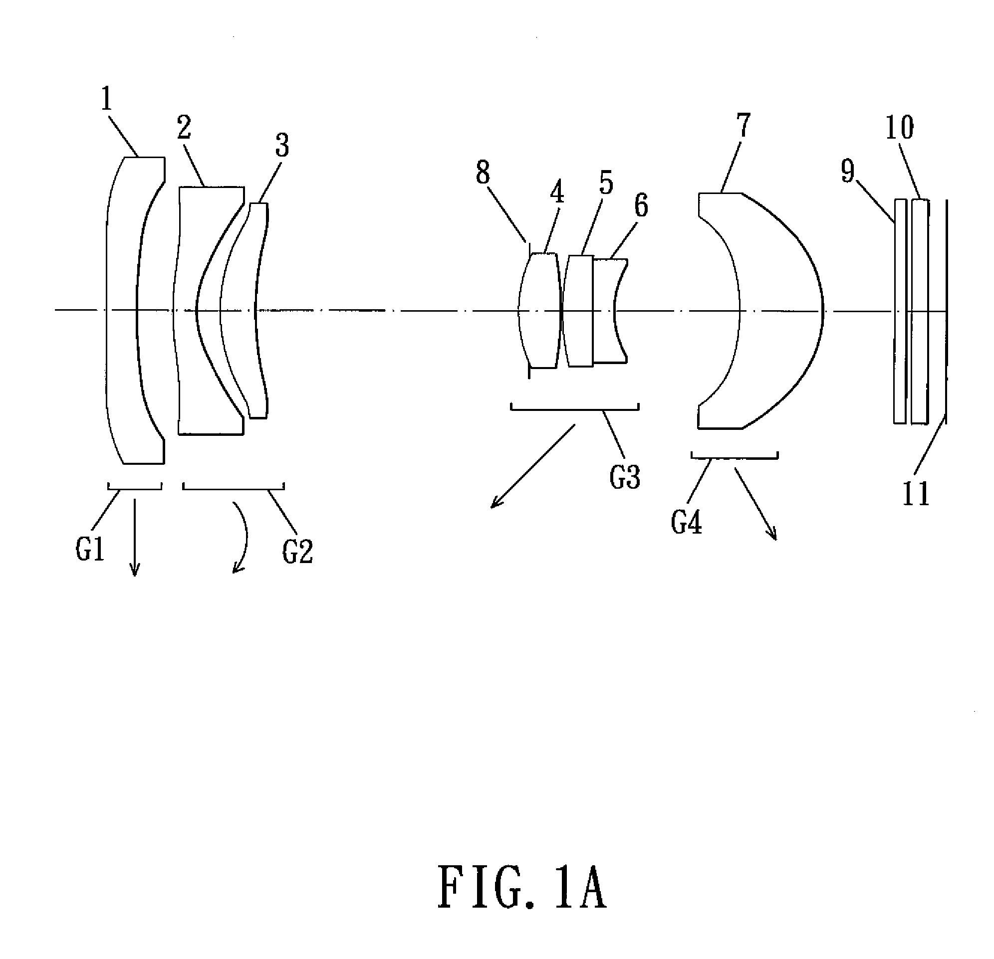
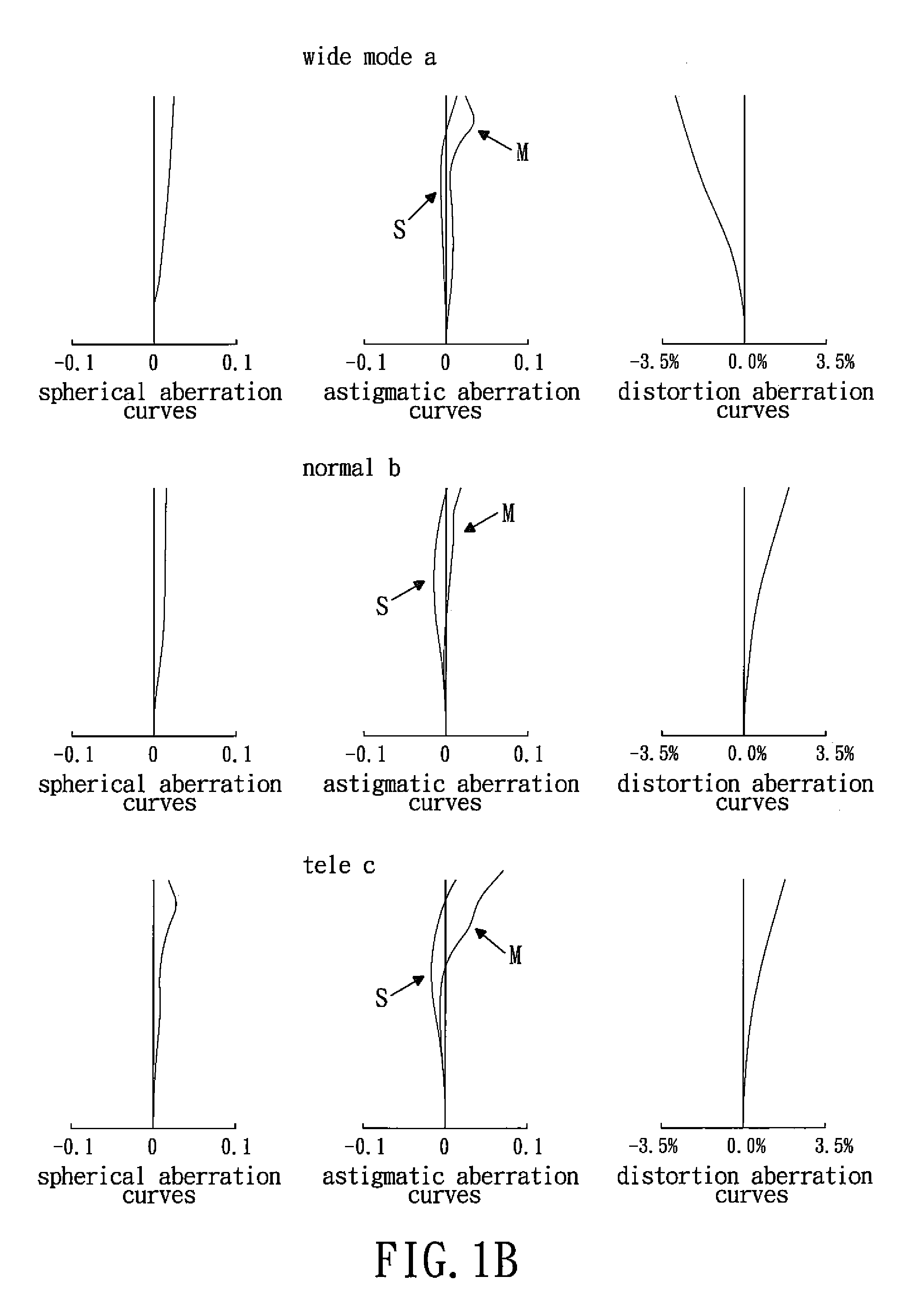
[0039]A focal length f of the zoom lens system f=5.07 mm˜9.35 mm˜14.49 mm, aperture stop value F=3.11˜4.50˜5.90, field of view 2ω=59.9˜33.1˜21.7 degrees, and zoom ratio=2.86, and these are the data in the modes of wide, mid and tele, respectively. As shown in table 1A, the numbers 1, 2, 3 . . . 19 represent the sequence numbers of the respective surface of the zoom lens system from the object to image side. r represents the radius of curvature (paraxial radius of curvature, its unit is mm), d (mm) is a distance between surfaces, nd is the index of refraction, and vd means reciprocal dispersion of the respective optical materials of the respective embodiments of the zoom lens system. And table 1B shows the aspheric surface coefficients of the respective surfaces of the respective embodiments of the zoom lens system.

[0040]TABLE 1Ardndvd1∞0.751.5135756.8217.2700.89~2.46~2.2136.6900.651.5434056.542.4400.5853.8360.851.6073026.666.4456.86~2.4...

Example

[0047]The second embodiment related description:

[0048]A focal length f of the zoom lens system f=5.06 mm˜9.43 mm˜14.27 mm, aperture stop value F=3.05˜4.51˜5.78, field of view 2ω=60.0˜32.8˜22.1 degrees, and zoom ratio=2.82, and these are the data in the modes of wide, mid and tele, respectively. Table 2A shows the data of the respective lens elements. And table 2B shows the aspheric surface coefficients of the respective surfaces of the respective embodiments of the zoom lens system. Both surfaces of the fifth and sixth lens elements 5, 6 are spherical, and the surfaces of other lens elements are plastic and aspheric.

[0049]TABLE 2Ardndvd1∞0.571.5135756.8210.9800.89~2.32~0.8935.6340.571.5434056.542.6630.3854.2040.671.6320023.466.2836.27~2.02~0.667∞−0.2683.4351.001.5920167.09−9.1920.05106.0020.791.8830040.811−40.3570.011.5140038.812−40.3570.641.7173629.5132.2583.27~6.79~9.6514−5.1191.941.5135756.815−2.5461.32~0.63~0.5516∞0.301.5168064.217∞0.1018∞0.401.5168064.219∞0.50

[0050]TABLE 2BSurf...

Example

[0051]The third embodiment related description:

[0052]A focal length f of the zoom lens system f=5.05 mm˜9.42 mm˜14.32 mm, aperture stop value F=2.84˜4.20˜5.40, field of view 2ω=60.1˜32.8˜22.0 degrees, and zoom ratio=2.84, and these are the data in the modes of wide, mid and tele, respectively. Table 3A shows the data of the respective lens elements. And table 3B shows the aspheric surface coefficients of the respective surfaces of the respective embodiments of the zoom lens system. Both surfaces of the fifth and sixth lens elements 5, 6 are spherical, and the surfaces of other lens elements are plastic and aspheric.

[0053]TABLE 3Ardndvd11573.8340.571.5135756.8211.0130.89~2.34~0.8935.7130.571.5434056.542.6960.3854.0290.661.6320023.465.7876.34~2.08~0.717∞−0.3183.4351.051.6188163.99−9.1920.05106.0020.811.8830040.811−40.3570.011.5140038.812−40.3570.591.7173629.5132.2583.33~6.83~9.7114−5.1191.911.5135756.815−2.5461.25~0.57~0.5116∞0.301.5168064.217∞0.1018∞0.401.5168064.219∞0.50

[0054]TABLE ...


PUM


Abstract

A zoom lens system comprises: a first lens group with a negative refractive power, a second lens group with a negative refractive power, a third lens group with a positive refractive power and a fourth lens group with a positive refractive power. When zooming between the wide mode and the tele mode, the second, third, and fourth lens groups move along the optical axis, the zoom lens system of the present invention can truly be miniaturized, and the zoom ratio is ensured within 2.8-3.0.

Description

BACKGROUND OF THE INVENTION[0001]1. Field of the Invention[0002]The present invention relates to a lens system, and more particularly to a zoom lens system which is suitable for used in the digital products.[0003]2. Description of the Prior Art[0004]So far, the lens system used in DC (digital camera) with a zoom ratio of three times is generally a three-group type lens system which is widely used, such as the zoom lens systems disclosed in JP Publication Nos 2000-267009, 2005-037727, 2005-070696 and 2007-079326, and these conventional zoom lens systems comprises, from the object side: a first lens group with a negative refractive power, a second lens group with a positive refractive power, and a third lens group with a positive refractive power. The first, second and third groups of lens elements move along the optical axis to accomplish zooming. After further study, we found that the above conventional lens systems still have the following problems:[0005]JP Publication Nos 2000-267...

Claims


Application Information

Patent Timeline
IPC IPC(8): G02B15/14G02B27/64G02B9/00G02B9/34
CPCG02B15/177G02B15/144513
Inventor NODA, SAYURI
Owner LARGAN PRECISION
Why Eureka
Try Eureka