Methods and devices for signal synchronization

Inactive Publication Date: 2007-07-05
BEYOND INNOVATION TECH
View PDF4 Cites 9 Cited by
  • Summary
  • Abstract
  • Description
  • Claims
  • Application Information

AI Technical Summary

Benefits of technology

[0017]In an embodiment of the invention, a signal transmitted between the first terminal and the second terminal is a bit stream signal or packet signal. If the signal is a packet signal and the second terminal cannot receive the output signal from the first terminal synchronously, the signal synchronization method further comprises adjusting length of heads of the packet signal, adjusting length of data of the packet signal, or dividing or integrating the packet signal. Adjustment of length of heads of the packet signal further comprises increasing length of heads of the packet signal when the receiving speed of the second terminal exceeds the output speed of the first terminal and decreasing length of heads of the packet signal when the receiving speed of the second terminal is lower than the output speed of the first terminal. Adjustment of length of data of the packet signal further comprises increasin

Problems solved by technology

The clocks generated by the PLL, however, generate considerable noise.
As a result, a rec

Method used


Image

  • Methods and devices for signal synchronization
  • Methods and devices for signal synchronization
  • Methods and devices for signal synchronization

Examples


Example

[0038]The following description is of the best-contemplated mode of carrying out the invention. This description is made for the purpose of illustrating the general principles of the invention and should not be taken in a limiting sense. The scope of the invention is best determined by reference to the appended claims.

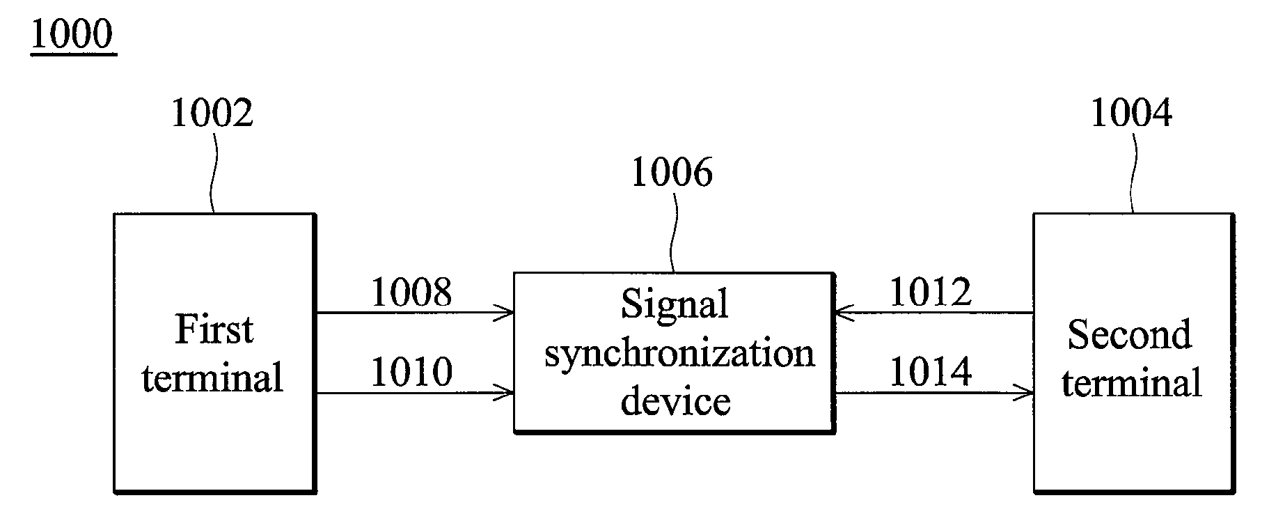
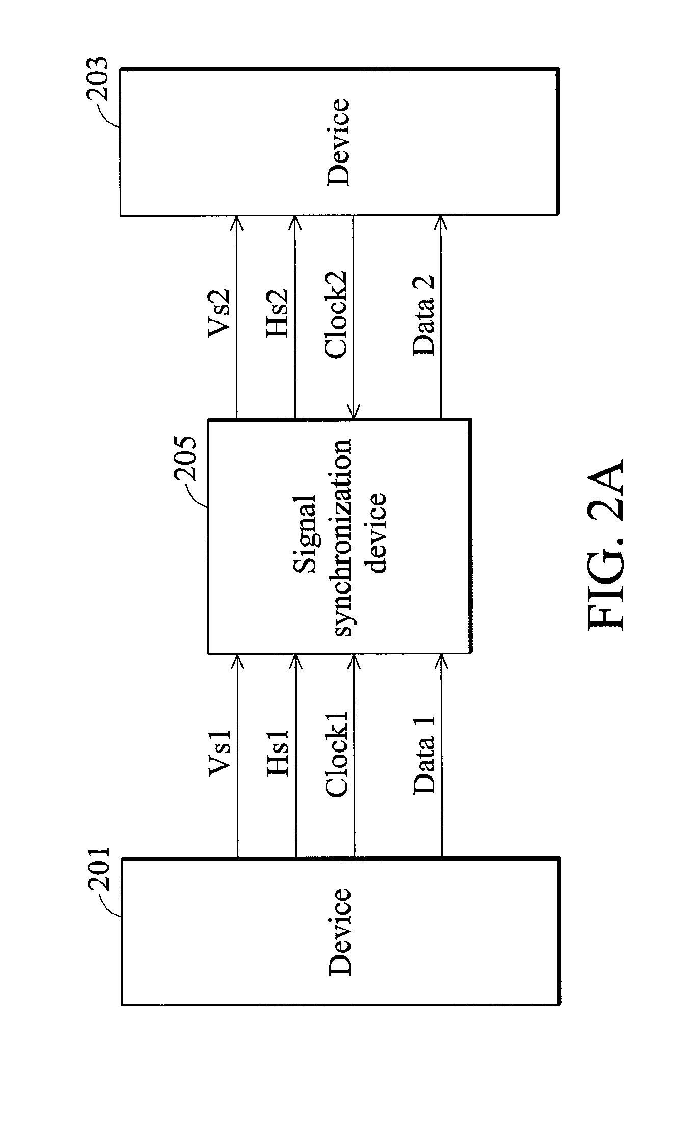
[0039]FIGS. 2A and 2B are block diagrams of a signal synchronization device in an image system according to an embodiment of the invention. In FIG. 2A, device 201 provides horizontal synchronous signal Hs1, vertical synchronous signal Vs1 and data Data1 to device 203. The signal synchronization device 205 adjusts horizontal synchronous signal Hs1, vertical synchronous signal Vs1 and data Data1 according to clock signals Clock1 and Clock2 from devices 201 and 203 such that device 203 receives the adjusted signals, horizontal synchronous signal Hs2, vertical synchronous signal Vs2 and data Data2. Device 203 is synchronized with data Data1 via the adjustment. It is noted ...


PUM


Abstract

A signal synchronization device and signal synchronization method are provided. The method comprises determining whether a receiving device can receive data output from an output device synchronously and adjusting the dummy period of the signal, which will be received by the receiving device, when the data output from the output device cannot be received by the receiving device synchronously.

Description

BACKGROUND OF THE INVENTION[0001]1. Field of the Invention[0002]The invention relates to a method and device for signal synchronization, and in particular, to a method of adjusting a dummy period to make a receiving device to receive data from an output device synchronously.[0003]2. Description of the Related Art[0004]Currently, phase locked loops (PLLs) remain a core of clock generators. A clock generator generates clocks of different frequencies by phase locked loops (PLLs), receiving the same base frequency provided by a crystal, associated with different frequency dividers such that multiple crystal oscillators in a conventional system are replaced.[0005]A phase locked loop (PLL) has two input terminals respectively receiving a reference frequency Fref and a feedback frequency Fvco and an output terminal receiving an output frequency Fout. The relationship between the frequencies is expressed as Fout=(Fref×P) / (Q×N).[0006]A phase locked loop (PLL), a negative feedback system, com...

Claims


Application Information

Patent Timeline
IPC IPC(8): G09G5/00
CPCG09G5/008H03L7/00H04L7/0012H04N5/12H04L7/033H04L2007/045H04L7/0083
Inventor SHEN, CHUNG-LI
Owner BEYOND INNOVATION TECH
Why Eureka
Try Eureka