Toilet flushing device and flush toilet

Inactive Publication Date: 2013-11-07
LIXIL CORP
View PDF10 Cites 9 Cited by
  • Summary
  • Abstract
  • Description
  • Claims
  • Application Information

AI Technical Summary

Benefits of technology

[0038]The third tank is provided with the inlet so that flush water can flow from a lower part of the first tank into the third tank. Accordingly, air is not allowed to flow from the first tank through the inlet into the third tank until the water level of the flush water in the first tank drops below the inlet of the third tank. Consequently, the third tank can be kept full of flush water by the influence of pressure of flush water in the first tank. In other words, almost all the flush water in the first tank can be caused to flow into the third tank. The flush water having flowed in the third tank can be supplied through the water-supply passage into the toilet body by the let pump. Consequently, the toilet flushing device can supply flush water to the toilet body at a high flout rate. Thus, the toilet flushing device can use almost all the flush water stored in the first and third tanks and can desirably execute toilet flushing.
[0039]Furthermore, although the jet pump is disposed in an upper interior of the third tank, since the third tank can be kept full of flush water until almost all the flush water in the first tank flews into the third tank, the jet pump can draw the flush water in the third tank in the interim with the result that flush water can be supplied to the water-supply passage.
[0040]Further

Problems solved by technology

As a result, there is a possibility that the hollow pipe cannot desirably suck air in the toilet drainage for occurrence and continuation of siphon effect in the toilet drainage.
Furthermore, the negative force in the toilet drainage is rendered stronger than the suction power of the hollow pipe after occurrence of the siphon effect i

Method used


Image

  • Toilet flushing device and flush toilet
  • Toilet flushing device and flush toilet
  • Toilet flushing device and flush toilet

Examples


Example

Embodiment 1

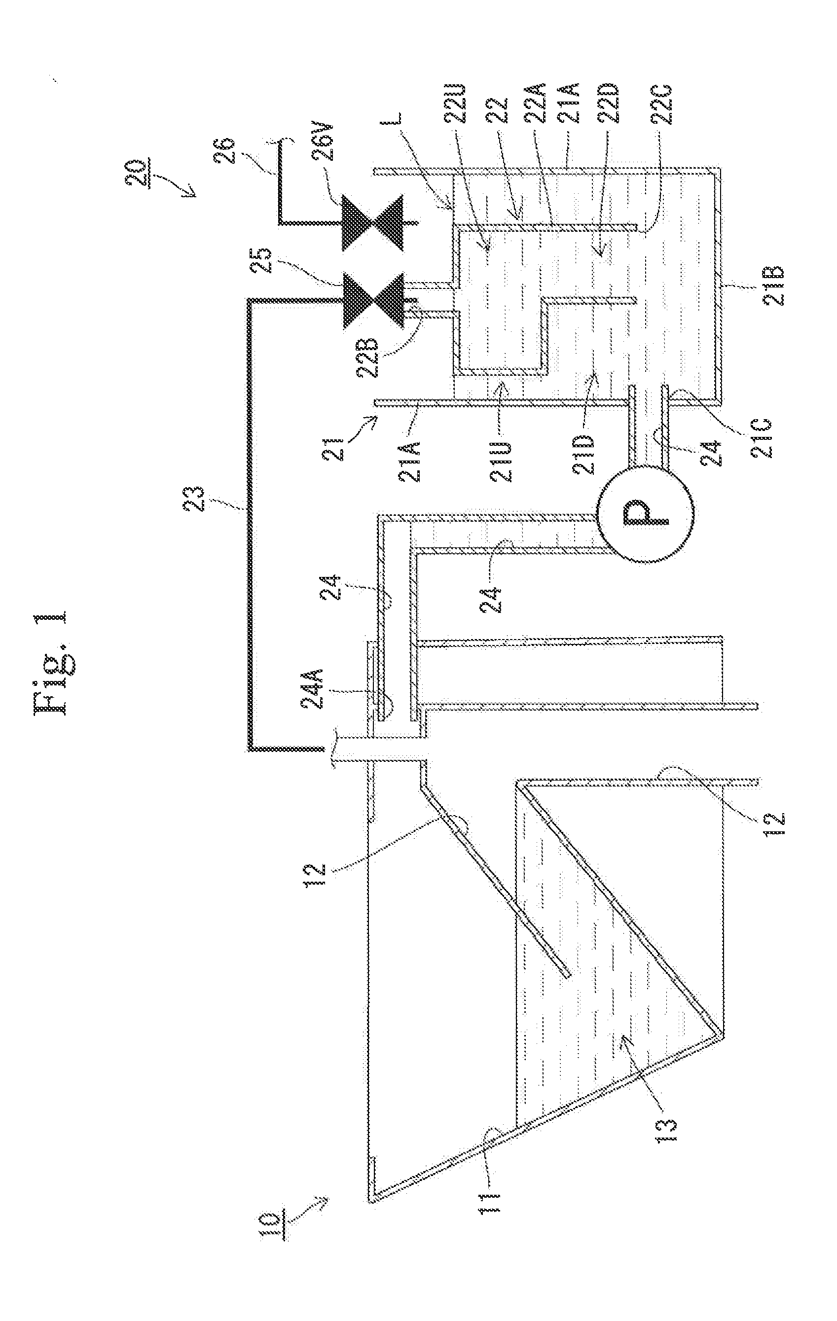
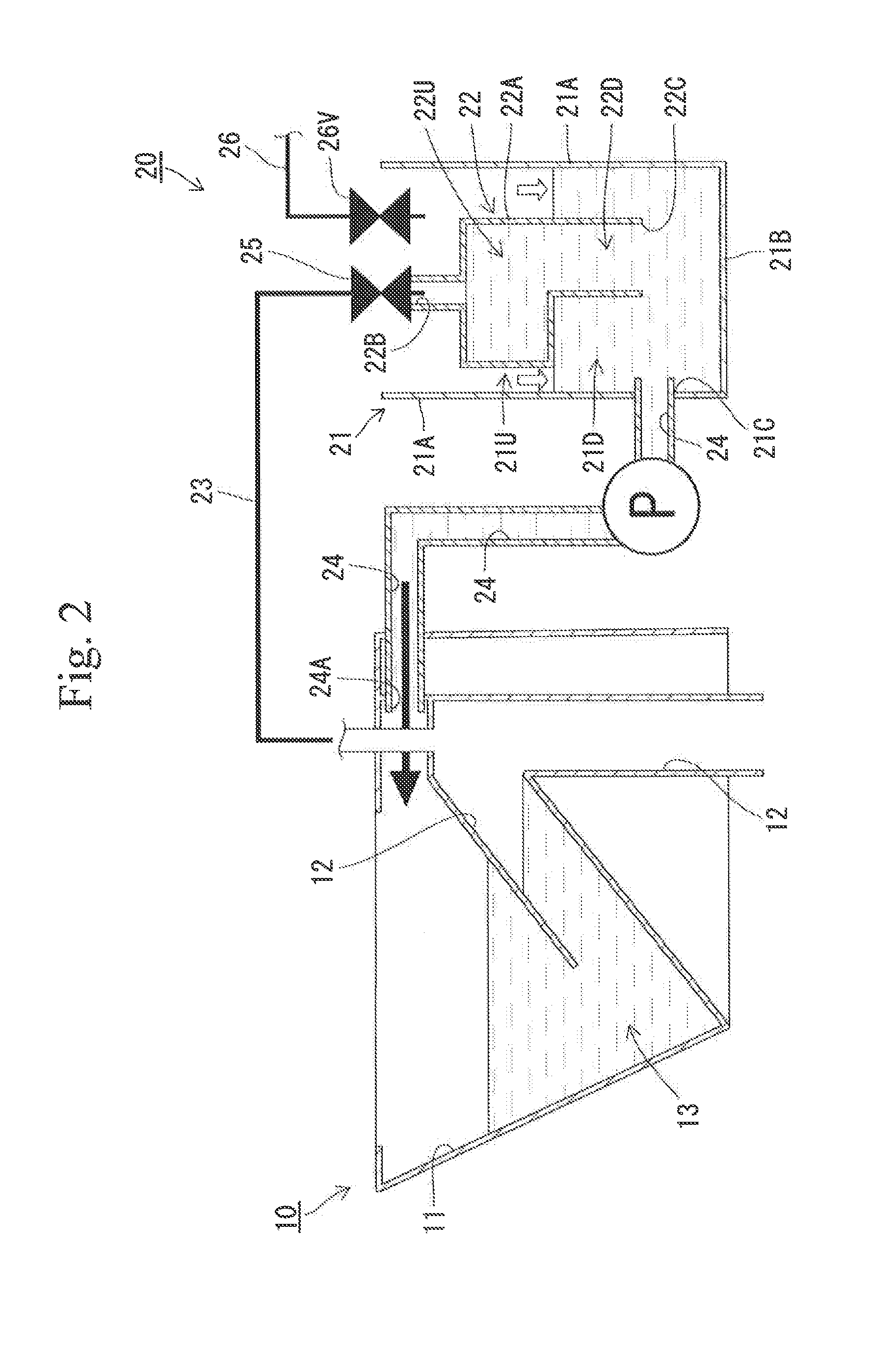
[0075]The flush toilet of embodiment 1 includes a toilet body 10 and a toilet flushing device 20 supplying flush water to the toilet body 10 as shown in FIG. 1. The toilet body 10 includes a toilet bowl 11 and a toilet drainage 12 communicating with a downstream side of the toilet bowl 11. A water sealing portion 13 retaining flush water is formed by a lower part of the toilet bowl 11 and an upstream of the toilet drainage 12.

[0076]The toilet flushing device 20 is located in the rear of the toilet body 10 and a large part of the toilet flushing device 20 is disposed lower than an upper surface of the toilet body 10. Consequently, the flush toilet achieves low silhouette. The toilet flushing device 20 includes a first tank 21, a second tank 22, an air passage 23, a water-supply passage 24 and an on-off valve 25 serving as a delay unit.

[0077]The first tank 21 has an upper end which is upwardly open and includes a vertically extending peripheral wall 21A and a bottom wall 2...

Example

Embodiment 2

[0098]A flush toilet according to embodiment 2 differs from embodiment 1 in that the toilet flushing device 30 includes a third tank 32 and flush water stored in the first tank 31 is supplied into the toilet body 10 by making use of a jet pump 33, as shown in FIG. 7. The other configuration of the flush toilet is the same as that of embodiment 1 and accordingly, an identical or similar structure is labeled by the same reference symbol as that in embodiment 1 and detailed description of such structure will be eliminated.

[0099]The toilet flushing device 30 is located in the rear of the toilet body 10 and a large part of the toilet flushing device 30 is disposed lower than an upper surface of the toilet body 10. Consequently, the flush toilet achieves low silhouette. The toilet flushing device 30 includes a first tank 21, a second tank 22, an air passage 23, a water-supply passage 24, an on-off valve 25 serving as a delay unit, a third tank 32 and a jet pump 33.

[0100]The fi...

Example

Embodiment 3

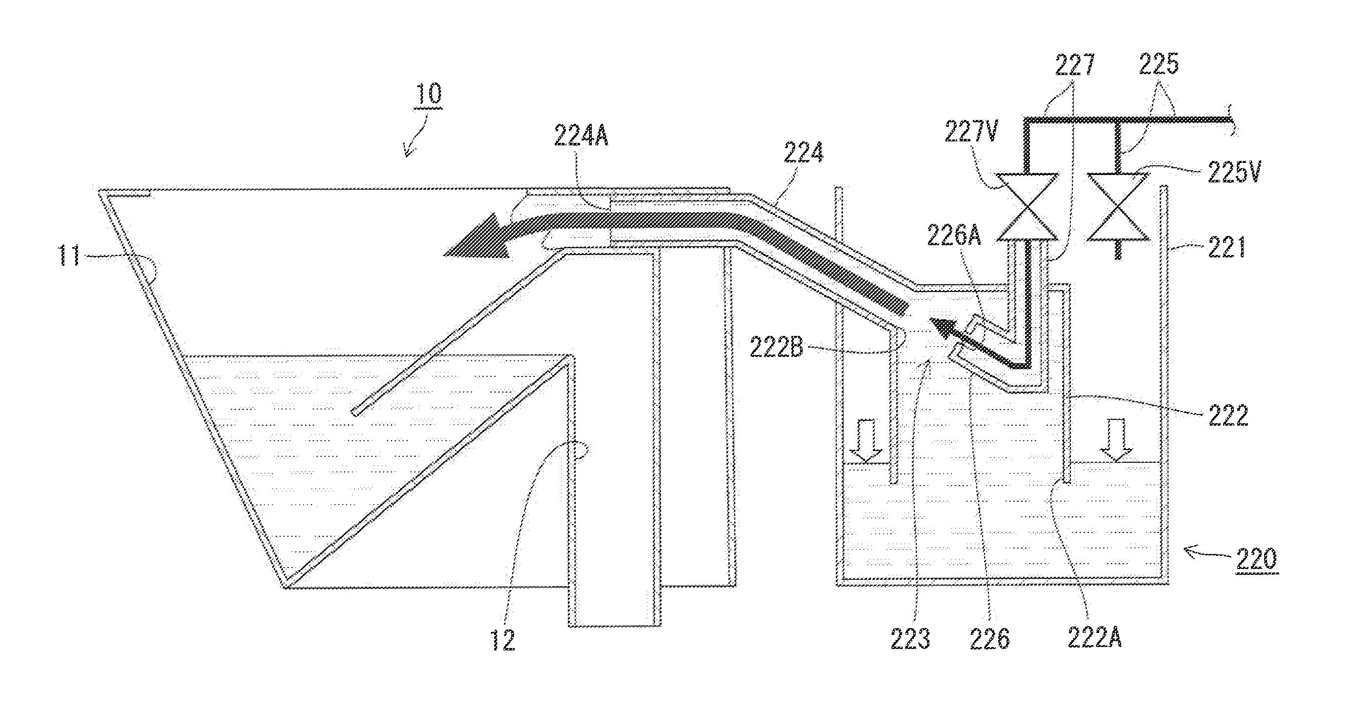
[0135]The flush toilet according to the third invention includes the toilet body 10 and a toilet flushing device 300 as shown in FIG. 15. The toilet body 10 includes the toilet bowl 11 and the toilet drainage 12 communicating with the downstream side of the toilet bowl 11. The toilet bowl 11 has a rim water passage 14 formed along an opening edge of the upper side. The toilet drainage 12 has an upstream end communicating with a lower end of the toilet bowl 11. The toilet drainage 12 includes a region from a top thereof (a highest part) to the lower end of the toilet bowl 11. The region serves as water sealing, portion 13. The toilet drainage 12 has an air flow hole 15 which is located downstream with respect to the water sealing portion 13 and open above the water sealing portion 13. The toilet drainage 12 further has a narrow portion 16 which is provided in a region extending downward from the air flow hole 15 and has a reduced diameter.

[0136]The toilet flushing device ...


PUM


Abstract

Providing a toilet flushing device and a flush toilet both of which can desirably execute toilet flushing. A toilet flushing device (20) includes a first tank (21) storing flush water, a second tank (22) having a lower opening (22C) communicating with the first tank (21) and having a lower region (22D) and an upper region (22U) with a larger capacity per unit height than the lower region (22D), an air passage (23) communicating between the second tank (22) and a toilet drainage (12) via a position located higher than a maximum storage water level (L) in the first tank (21), a water-supply passage (24) communicating between the first tank (21) and a toilet bowl (11) and a on-off valve (25) which maximizes a flow rate of an air in the air passage (23) with a delay to initiation of supply of flush water stored in the first tank (21) through the water-supply passage (24) into the toilet bowl (11), the air flowing from the toilet drainage (12) side to the second tank (22) side.

Description

TECHNICAL FIELD[0001]The present invention relates to a toilet flushing device and a flush toilet.BACKGROUND ART[0002]Patent Document 1 discloses a conventional flush toilet provided with a toilet body and a toilet flushing device. In this flush toilet, the toilet flushing device supplies flush water to the toilet body to execute toilet flushing. The toilet body has a toilet bowl and a toilet drainage communicating with a downstream side of the toilet bowl. The toilet flushing device has a tank, a hollow pipe, an exhaust passage and a water-supply path. The tank is provided for storing flush water to be supplied to the toilet body. The hollow pipe is accommodated in the tank so as to extend vertically and has a lower end which is open in the tank. The exhaust passage communicates between an upper end of the hollow pipe and the toilet drainage of the toilet body through a location located higher than a maximum storage water level in the tank. The water-supply path communicates betwee...

Claims


Application Information

Patent Timeline
IPC IPC(8): E03D11/18E03D11/02
CPCE03D11/18E03D11/02E03D1/24E03D3/10E03D5/01E03D5/10E03D11/08E03D5/02E03D5/12
Inventor KITAMURA, SATOSHIWATARI, KOJIROYAMAI, HITOMIHAIDA, SHUHEISAKAKIBARA, KEISUKE
Owner LIXIL CORP
Why Eureka
Try Eureka