

Terminal fitting and a wire connected with a terminal fitting
- Summary
- Abstract
- Description
- Claims
- Application Information
AI Technical Summary
Benefits of technology
Problems solved by technology
Method used
Image

Examples
first embodiment
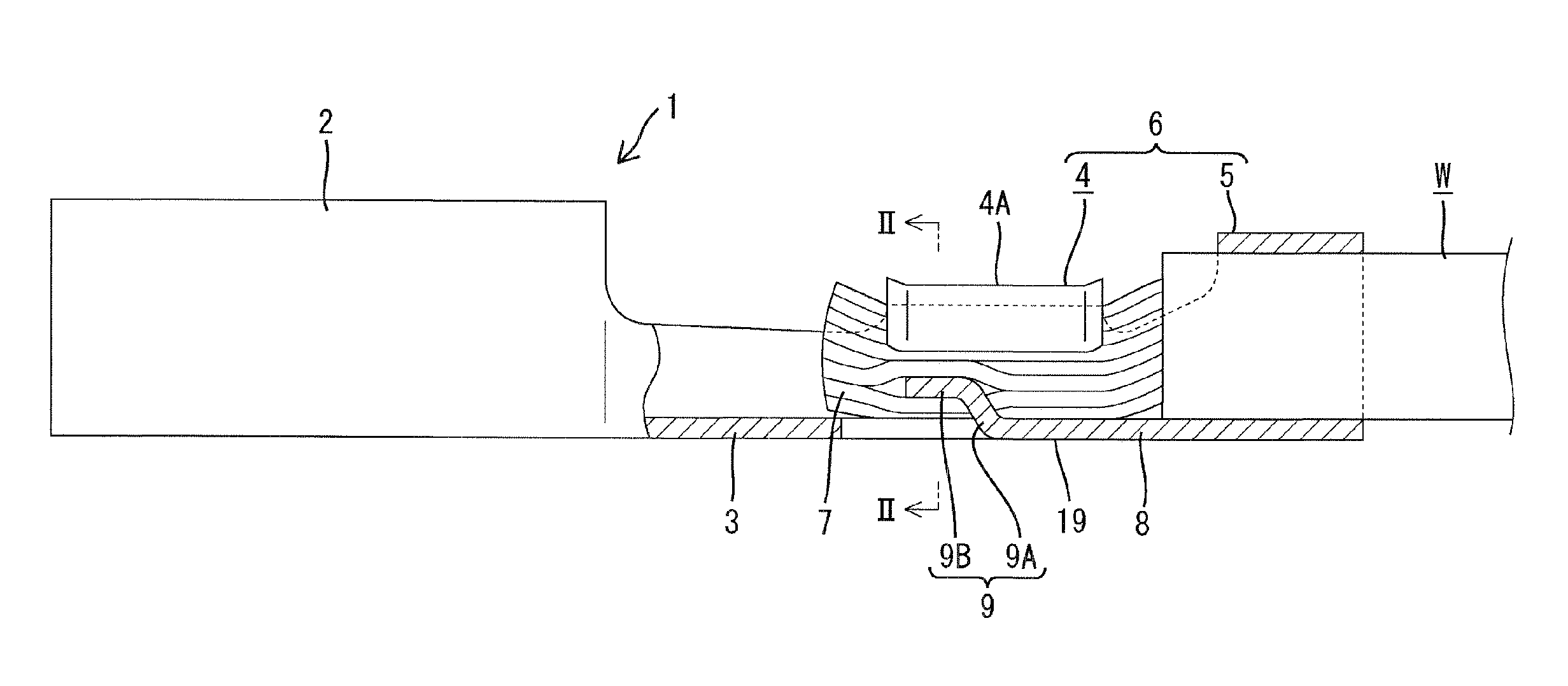
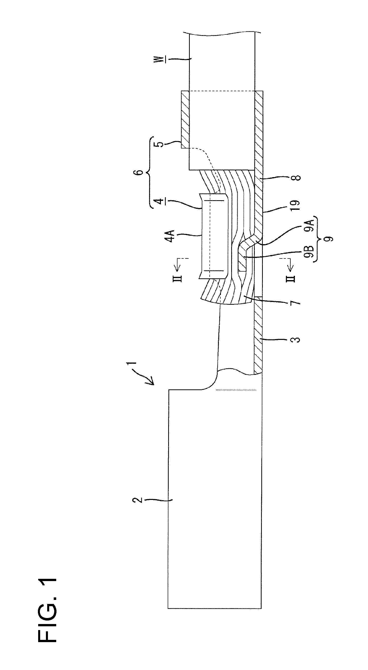
[0044]the invention is described with reference to FIGS. 1 to 3. Identified by 1 in FIG. 1 is a female terminal fitting made of a flat plate material e.g. of a copper metal. A box portion 2 for connection with a mating terminal fitting is formed in a front portion of the female terminal fitting. A crimping portion 6 to be crimped, bent or folded into connection with a wire W is formed behind the box portion 2 via a connecting portion 3. The crimping portion 6 includes a wire barrel 4 and an insulation barrel 5 located one behind the other. The wire barrel 4 is to be crimped, bent or folded into connection with a core 7 exposed near an end portion of the wire W, and the insulation barrel 5 is to be crimped, bent or folded into connection with an insulated part of the wire. A coupling 8 is formed between the barrels 4 and 5. The core 7 is formed by twisting metal strands and surrounding the strands by a coating.
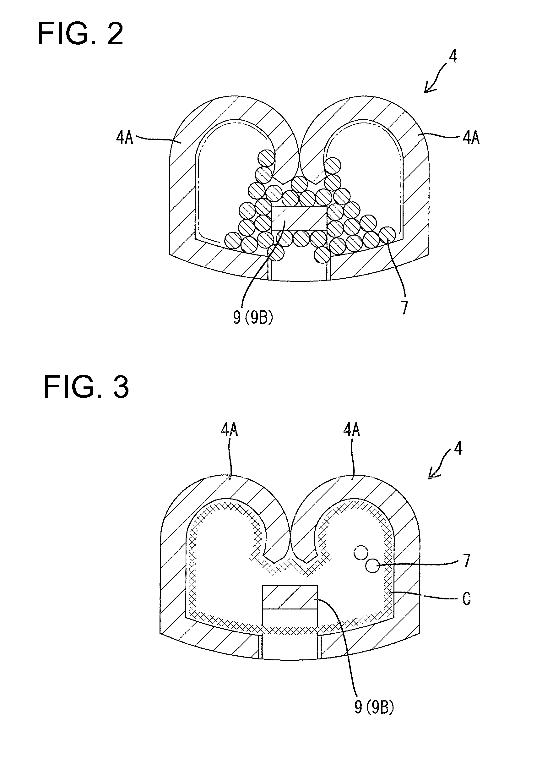
[0045]The wire barrel 4 includes two barrel pieces 4A projecting in a widt...
third embodiment
[0052]FIG. 6 shows the invention. In this embodiment, the base end of a deep conductive piece 11 is arranged on a connecting portion 3 between the box 2 and the wire barrel 4 at a position before the leading end of a core 7. The deep conductive piece 11 has a base end fixed at this position preferably by welding or soldering, or by cutting and bending. The deep conductive piece 11 then extends obliquely back toward the interior of the wire barrel 4 and the center of a core 7 while biting into a clamp boundary layer C.
[0053]The third embodiment has functions and effects similar to the other embodiments. Additionally, the base end of the deep conductive piece 11 where water might intrude is located outside the wire barrel 4 to avoid water influences on the core 7.
fourth embodiment
[0054]FIG. 7 shows the invention. In this embodiment, a deep conductive piece 12 is formed separately from a terminal fitting. The deep conductive piece 12 is formed by cutting an upper surface of an inverted U-shaped clamp piece 13 that is mounted on a connecting portion 3 of the terminal fitting from above and bending the cut portion. The deep conductive piece 12 extends obliquely down toward a bottom wall 19 of the crimping portion 6 and toward the center of a core 7 in a wire barrel 4.
[0055]The clamp piece 13 of the fourth embodiment is mounted on the terminal fitting before the core 7 is fastened, thereby locating the deep conductive piece 12 in the wire barrel 4. The core 7 then is fastened.
[0056]The fourth embodiment exhibits functions and effects similar to those of the other embodiments. Additionally, the separate formation of the deep conductive piece 12 enables existing terminal fittings to be utilized.
[0057]The following embodiments also are included in the technical sco...
PUM
 Abstract
Description
Claims
Application Information