Light-emitting cell module

a technology of light-emitting cells and modules, applied in the direction of contact members penetrating/cutting insulation/cable strands, lighting support devices, lighting and heating apparatus, etc., can solve the problems of high manufacturing cost, large length of decoration lights, and time-consuming to manufacture the above decoration lights

Inactive Publication Date: 2008-10-28
SUPER LINK ELECTRONICS
View PDF9 Cites 28 Cited by
  • Summary
  • Abstract
  • Description
  • Claims
  • Application Information

AI Technical Summary

Problems solved by technology

It is time-consuming to manufacture the above decoration lights.
In addition, the manufacturing cost is relatively high.
Also, such decoration light generally has a considerable length.
In addition, it takes more time to manufacture the decoration lights and the manufacturing cost is increased.

Method used


Image

  • Light-emitting cell module
  • Light-emitting cell module
  • Light-emitting cell module

Examples


Embodiment Construction

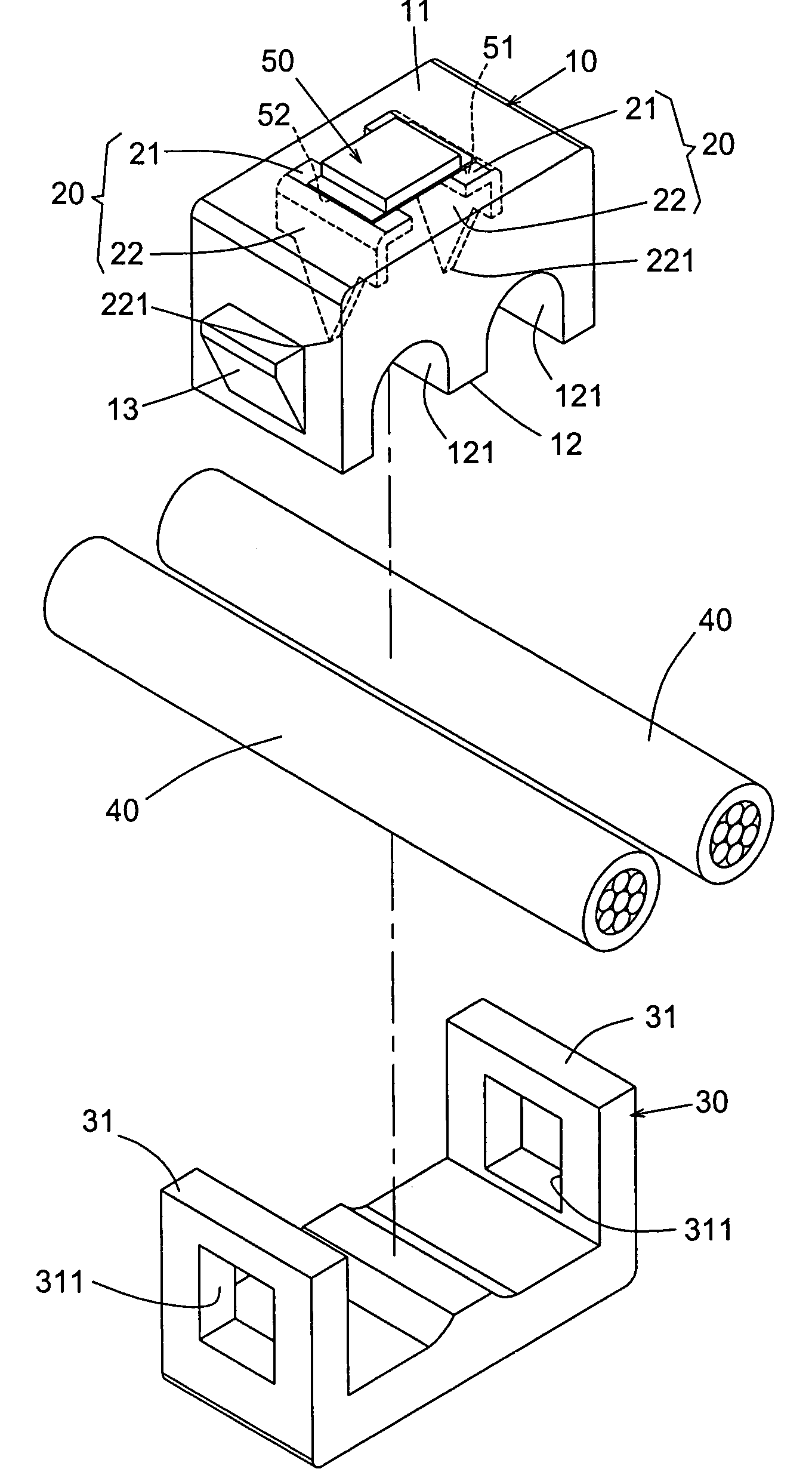
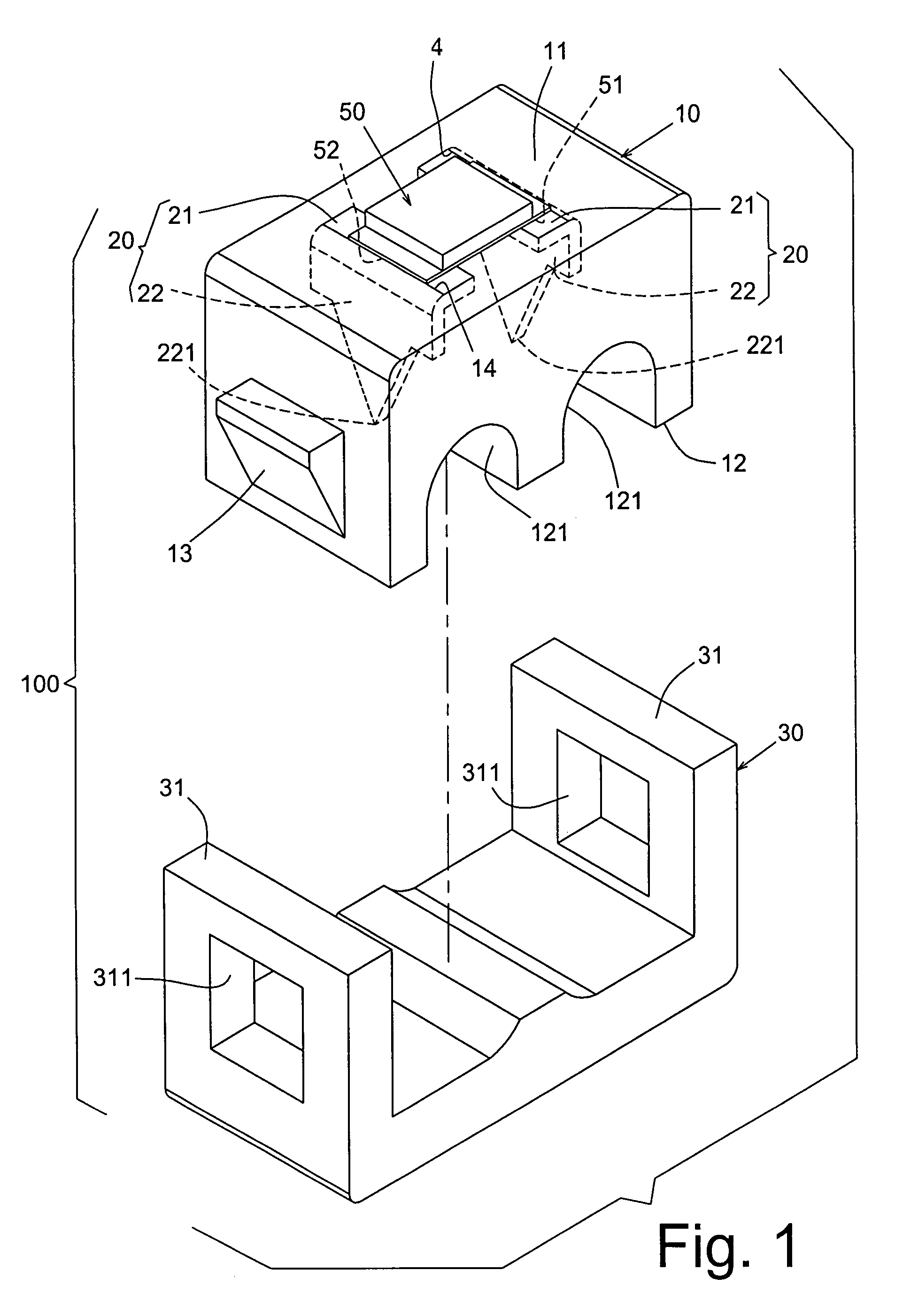
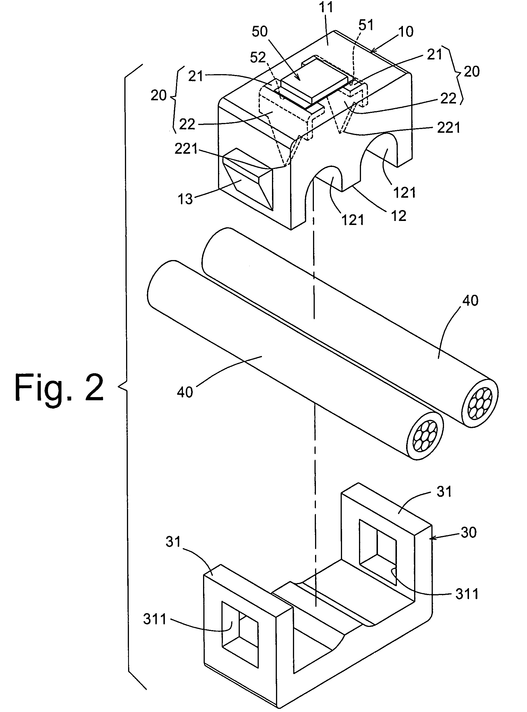
[0016]Please refer to FIGS. 1 to 5. The light-emitting cell module 100 of the present invention includes: a base seat 10; multiple terminals 20 respectively inlaid in the base seat 10, a first end 21 of each terminal 20 being exposed to outer side of a first end 11 of the base seat 10, a second end 22 of each terminal 20 having a sharp thrust section 221 protruding from a second end 12 of the base seat 10; a connecting seat 30 latched with the second end 12 of the base seat 10, the connecting seat 30 and the second end 12 of the base seat 10 together tightly clamping and holding multiple leads 40 of positive electrode and negative electrode, the second ends 22 of the terminals 20 being aligned with the corresponding leads 40, whereby the thrust sections 221 thrust into the leads 40 to electrically connect the terminals 20 with the leads 40 of positive electrode or negative electrode; and a light-emitting cell 50 such as a light-emitting diode (LED). The two pins 51, 52 of the light-...


PUM


Abstract

A light-emitting cell module includes a base seat and multiple terminals respectively inlaid in the base seat. A first end of each terminal being exposed to outer side of a first end of the base seat. A second end of each terminal having a sharp thrust section protruding from a second end of the base seat. A connecting seat latched with the second end of the base seat, the connecting seat and the second end of the base seat together tightly clamping and holding multiple leads of positive electrode and negative electrode, the second ends of the terminals being aligned with the corresponding leads, whereby the thrust sections of the second ends thrust into the leads to electrically connect the terminals with the leads. A light-emitting cell having two pins which are soldered with the first ends of the terminals of the positive electrode and the negative electrode.

Description

BACKGROUND OF THE INVENTION[0001]1. Field of the Invention[0002]The present invention is related to a light-emitting cell module in which a light-emitting cell such as a light-emitting diode is soldered between two terminals of a base seat. The base seat is latched with a connecting seat to tightly clamp the leads of different polarities in a desired position. The terminals inlaid in the base seat respectively thrust into the leads to electrically connect therewith. After powered on, the light-emitting cell is lighted up.[0003]2. Description of the Prior Art[0004]FIG. 7 shows the light-emitting diodes (LED) 63 of the conventional Christmas light, decoration light, etc. Two pins 631, 632 of the LED 63 soldered on two leads 61, 62. When powered on, the LED is lighted up. In manufacturing, the pins of the LED must be laboriously soldered with the leads 61, 62 one by one. It is time-consuming to manufacture the above decoration lights. In addition, the manufacturing cost is relatively h...

Claims


Application Information

Patent Timeline
Patent Type & Authority Patents(United States)
IPC IPC(8): H01R4/24
CPCF21S4/001F21V21/002H01R4/2404F21W2121/04F21Y2101/02F21S4/10F21Y2115/10H01L33/62H01R4/2406
Inventor LEE, IPSON
Owner SUPER LINK ELECTRONICS
Why Eureka
Try Eureka