Medical connector system

a technology of medical connectors and connectors, applied in the field of medical connector systems, can solve the problems of insufficient application, serious problems, and inability to achieve the required functions, and achieve the effect of reducing bacterial contamination and simple operation

Inactive Publication Date: 2008-11-18
JMS CO LTD
View PDF11 Cites 131 Cited by
  • Summary
  • Abstract
  • Description
  • Claims
  • Application Information

AI Technical Summary

Benefits of technology

[0008]It is an object of the present invention to provide a medical connector system that is capable of reducing the bacterial contamination with a simple operation when a channel for a solution is connected.

Problems solved by technology

The most serious problem to be addressed for carrying out the peritoneal dialysis is bacteria in the air or attached to the skin inadvertently entering into the abdominal cavity with the dialysis solution during the operation of exchanging the dialysis solution, which is required four times per day.
However, since these products necessarily require units dedicated to the products, a patient always has to carry the unit.
Moreover, in the event of problems with the unit, serious problems might occur.
However, all of those connectors known conventionally have problems that their mechanism is complicated, their size is large, and the required functions cannot be obtained sufficiently, and therefore none of them have been put into practical use.
In particular, there is no connector that is constructed by paying sufficient attention to the structure for preventing the bacterial contamination when the connecting and detaching are repeated.

Method used


Image

  • Medical connector system
  • Medical connector system
  • Medical connector system

Examples


Embodiment Construction

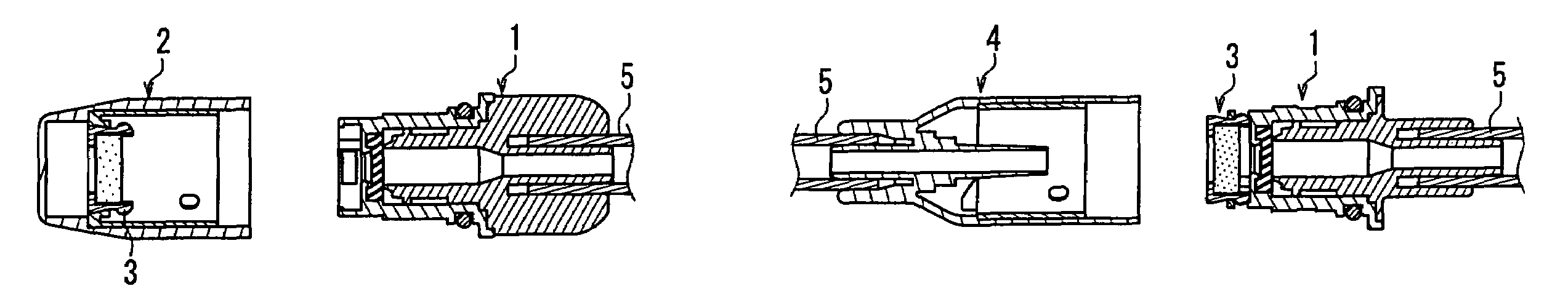
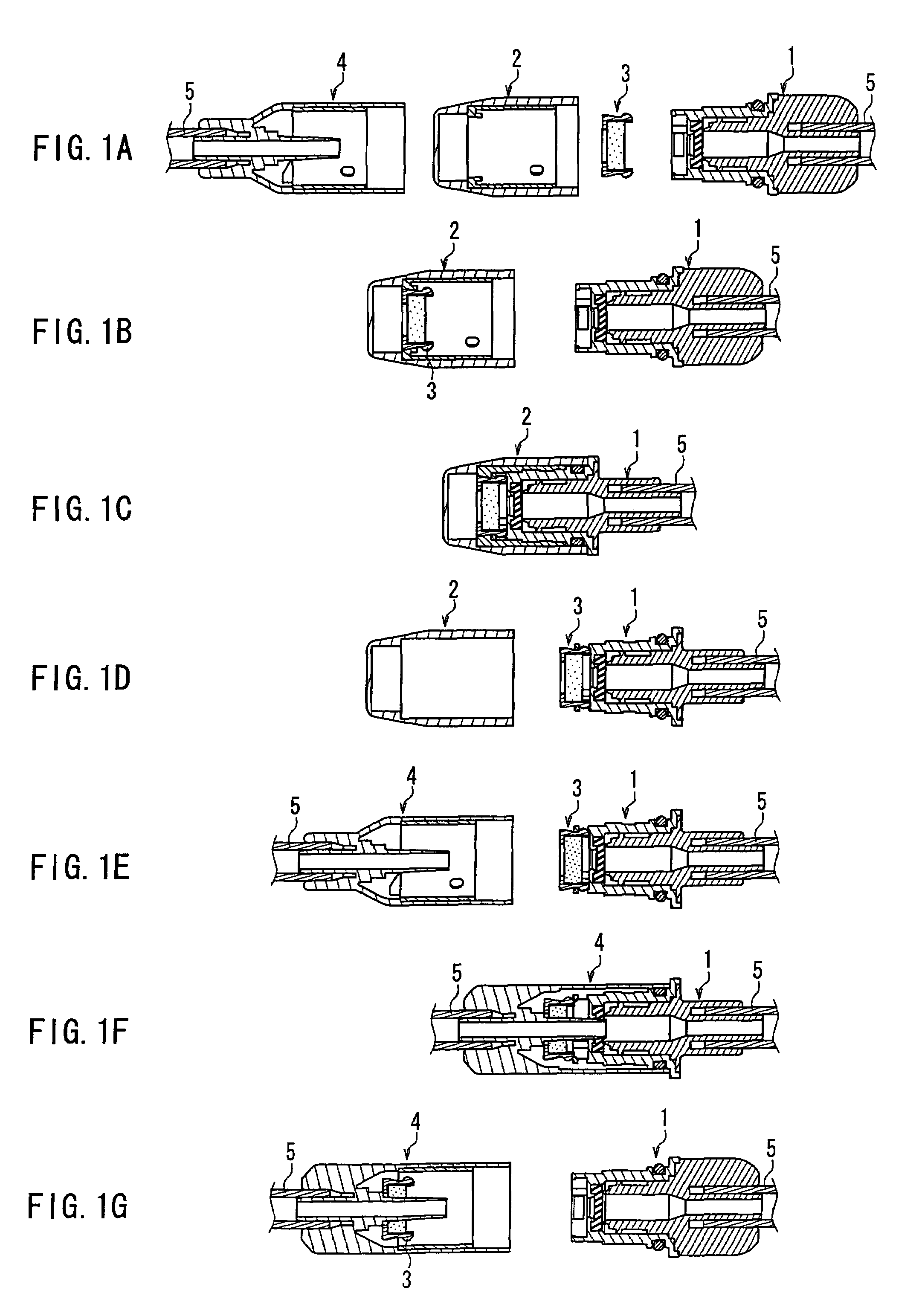
[0023]According to the medical connector system of the present invention having the above configuration, the disinfectant-impregnated member in the inner cap can prevent the bacterial contamination of the front end portion of the male type connector. Further, every time the protective cap is exchanged, the inner cap is exchanged into a new one, and therefore this system can be disinfected by a new disinfectant-impregnated member without a complicated procedure.

[0024]In the medical connector system according to the present invention, preferably, the female type connector includes an inner cap retaining portion, and when the connection between the male type connector and the female type connector is released, the inner cap is retained inside the female type connector by the inner cap retaining portion and is detached from the front end of the male type connector.

[0025]Preferably, the male type connector includes a septum member at the front end portion of the male type connector for s...


PUM


Abstract

There are provided a male type connector (1), a protective cap (2), an inner cap (3) that supports a disinfectant-impregnated member therein and is retained in the protective cap, and a female type connector (4) in which an inner cylinder is fixed at an end of an outer cylinder, the inner cylinder including an internal end portion located inside the outer cylinder and an exposed external end portion. The inner cap includes engaging legs at each of which an engaging convexity is formed. A front end portion of the male type connector allows the engaging convexities at the engaging legs to engage therewith from inside. An inner cap retaining portion is formed on an inner wall surface of the protective cap, and a force exerted by the engagement between the inner cap and the male type connector is larger than a force exerted by the inner cap retaining portion to retain the inner cap. When the protective cap with the inner cap retained therein is fitted with the male type connector, and then is removed from the male type connector, the inner cap is retained in the male type connector and is detached from the protective cap. When the male type connector is connected with the female type connector, the internal end portion of the inner cylinder penetrates through the disinfectant-impregnated member, so that a channel is opened. When the connecting and detaching are repeated, the bacterial contamination can be reduced with a simple operation.

Description

TECHNICAL FIELD[0001]The present invention relates to a medical connector system for connecting a tube or the like that forms a channel for a solution for medical use, for example. In particular, the present invention relates to a medical connector system provided with a function of securely disinfecting a connecting portion with a simple operation when the connecting and detaching are repeated.BACKGROUND ART[0002]Known examples of medical connectors include a connector for connecting a patient side transfer tube (extension tube) with a peritoneal dialysis unit when a dialysis solution for peritoneal dialysis is exchanged. Peritoneal dialysis is a medical treatment method in which a dialysis solution is stored in a patient's abdominal cavity by way of a peritoneal catheter that is implanted surgically in the patient's abdominal cavity beforehand, so that impurities accumulated in the body are filtered using capillary vessels in the peritoneum. The patient undertakes daily activities...

Claims


Application Information

Patent Timeline
Patent Type & Authority Patents(United States)
IPC IPC(8): A61M5/32A61M1/28A61M39/14A61M39/16
CPCA61M39/14A61M39/162A61M1/28A61M2039/1027A61M2039/1066A61M2039/1072A61M1/285Y10S604/905A61M39/10A61M39/00A61M5/14
Inventor MIYAHARA, HISEYASU
Owner JMS CO LTD
Why Eureka
Try Eureka