Axially compliant pressure roller utilizing non-newtonian fluid

a pressure roller and non-newtonian fluid technology, applied in the field of pressure rollers, can solve the problems of increasing local pressure and viscosity, and achieve the effects of reducing hydrodynamic force, reducing fluid viscosity, and increasing shear ra

Inactive Publication Date: 2008-12-16
SKC HAAS DISPLAY FILMS CO LTD +1
View PDF33 Cites 18 Cited by
  • Summary
  • Abstract
  • Description
  • Claims
  • Application Information

AI Technical Summary

Benefits of technology

[0013]The invention and its objects and advantages will become more apparent in the detailed description of the preferred embodiment presented below.

Problems solved by technology

A limited number of shear thickening non-Newtonian fluids are available and can be utilized as well but with this type fluid increased shear rate from gap reduction would result in increased viscosity and increased local pressure.

Method used


Image

  • Axially compliant pressure roller utilizing non-newtonian fluid
  • Axially compliant pressure roller utilizing non-newtonian fluid
  • Axially compliant pressure roller utilizing non-newtonian fluid

Examples


Embodiment Construction

[0022]The present invention will be directed in particular to elements forming part of, or in cooperation more directly with the apparatus in accordance with the present invention. It is to be understood that elements not specifically shown or described may take various forms well known to those skilled in the art.

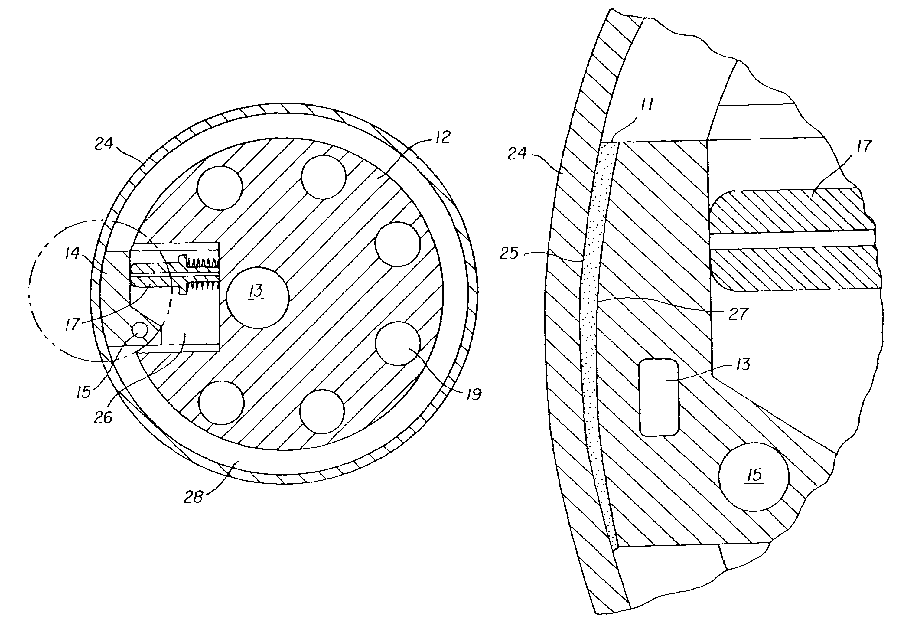
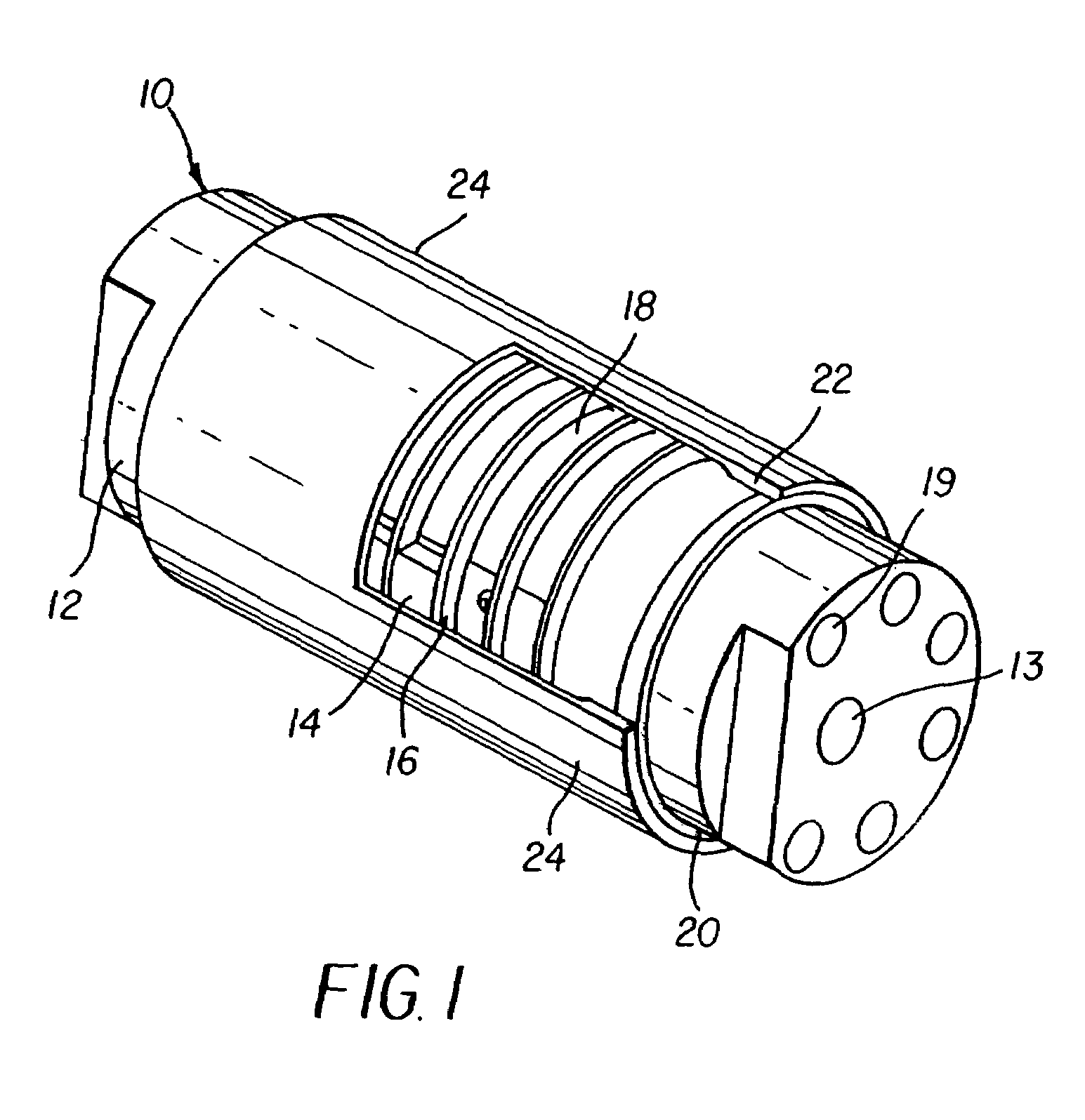
[0023]Referring now to FIG. 1 a compliant pressure roller is referred to in general by numeral 10. Compliant pressure roller 10 is comprised in general of a stationary inner core 12 and a plurality of shoes 14 which are pivotally mounted to the stationary inner core 12. A series of non-magnetic dividers 16 create a plurality of annular chambers 18 and each of the shoes 14 occupies one of the annular chambers 18.

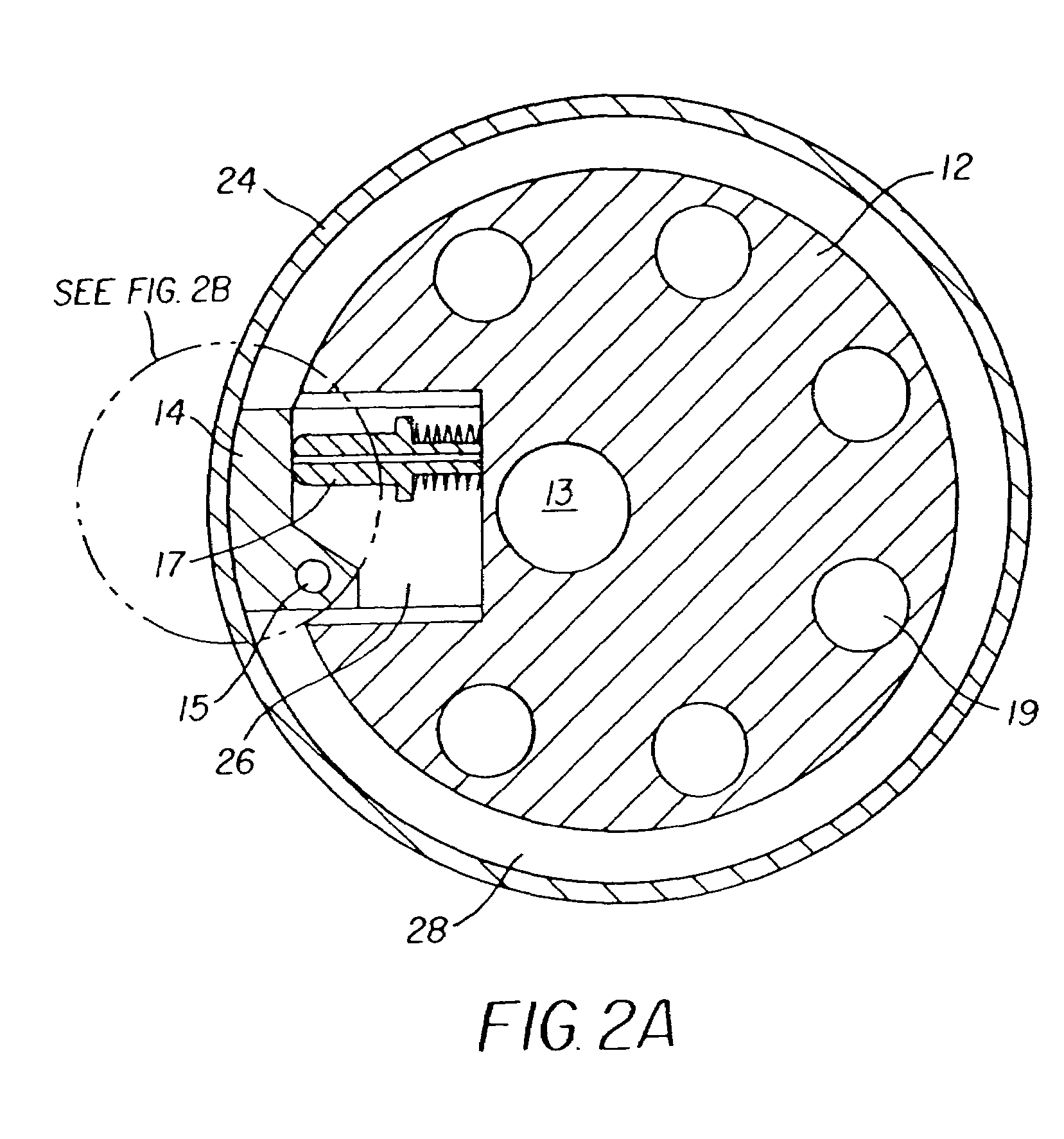
[0024]Referring to FIGS. 1, 2A, and 2B, shoe 14, which is eccentrically mounted, is shown. One surface of shoe 14 is curved. A pivot point 15 and spring loading assembly 17 are attached to shoe 14. A non-magnetic, metallic material is used in the construction of the...


PUM

PropertyMeasurementUnit
pressureaaaaaaaaaa
pressureaaaaaaaaaa
pressureaaaaaaaaaa

Abstract

A compliant pressure roller (10) for creating uniform pressure at a nip comprises a stationary inner core (12). A plurality of shoes (14) is pivotally mounted to the stationary inner core. Dividers (16) create a plurality of annular chambers (18) wherein each of the shoes occupies one of the chambers. A non-Newtonian fluid (70) fills each of the chambers. A plurality of actuators is connected to at least one of the shoes. A thin, rotatable shell surrounds the plurality of chambers, shoes, and stationary inner core.

Description

CROSS REFERENCE TO RELATED APPLICATIONS[0001]Reference is made to commonly-assigned copending U.S. patent application Ser. No. 10 / 795,010, filed Mar. 5, 2004, entitled COMPLIANT PRESSURE ROLLER WITH UNIFORM NIP PRESSURE, by Bomba et al., the disclosure of which is incorporated herein.FIELD OF THE INVENTION[0002]The present invention relates in general to pressure rollers, and in particular, to a compliant pressure roller which adjusts to deformation in a thin outer shell.BACKGROUND OF THE INVENTION[0003]In preparing certain substrates it is important that at least one surface have a smooth finish. Often this smooth finish requires very high tolerances. Prior art solutions to the problem of creating a smooth finish have not been completely satisfactory. One prior art solution has been to use elastomeric rollers. Elastomeric rollers, however, cannot be ground to the same high tolerance as metallic rollers.[0004]Another prior art solution-has used carrier webs having a smooth surface f...

Claims


Application Information

Patent Timeline
Patent Type & Authority Patents(United States)
IPC IPC(8): D21G1/02
CPCF16C13/024F16C13/028F16C17/03F16C33/10Y10T29/53039Y10T29/49547Y10T29/49771
Inventor BOMBA, RICHARD D.
Owner SKC HAAS DISPLAY FILMS CO LTD
Why Eureka
Try Eureka