Method and apparatus for injecting a fuel into a combustor assembly

a combustor and fuel injection technology, which is applied in the ignition of turbine/propulsion engines, lighting and heating apparatus, engine starters, etc., can solve the problems of increasing the temperature of the combustion chamber, reducing the temperature of the igniter, and high emissions of undesirable compounds in the combustion system, so as to eliminate selected emissions

Inactive Publication Date: 2008-12-30
THE BOEING CO
View PDF50 Cites 80 Cited by
  • Summary
  • Abstract
  • Description
  • Claims
  • Application Information

AI Technical Summary

Benefits of technology

[0008]According to various embodiments a combustion system for a gas powered turbine to substantially mix and combust a fuel, to assist in substantially eliminating selected emissions is disclosed. The combustion system includes an oxidizer flow pathway through which an oxidizer flows in a selected direction out an outlet into a combustion area. An injector plate disposed near the outlet and an injector port is defined by the injector plate. A fuel manifold region is operably associated with the injector plate. A fuel disposed in the injector manifold region is operable to be injected into the combustion area and substantially mix with the fuel before the fuel reaches an ignition temperature.

Problems solved by technology

Generally, these combustion systems have high emissions of undesirable compounds such as nitrous oxide compounds (NOX) and carbon containing compounds.
Nevertheless, NOX emissions still exist due to the initial preburning.
This reduces the temperature of the igniter, but still increases the temperature of the combustion chamber.
This greatly reduces control over where combustion occurs and the temperature in the combustion chamber
These emission side converters, however, are not one hundred percent efficient thereby still allowing NOX emissions to enter the atmosphere.
Also, these converters are expensive and increase the complexity of the turbine and power production systems.

Method used


Image

  • Method and apparatus for injecting a fuel into a combustor assembly
  • Method and apparatus for injecting a fuel into a combustor assembly
  • Method and apparatus for injecting a fuel into a combustor assembly

Examples


Embodiment Construction

[0027]The following description of various embodiments is merely exemplary in nature and is in no way intended to limit the invention, its application, or uses. Specifically, although the following combustor is described in conjunction with a terrestrial gas powered turbine, it may be used in other systems. Furthermore, the mixer and heat exchanger may be used in systems other than turbine systems.

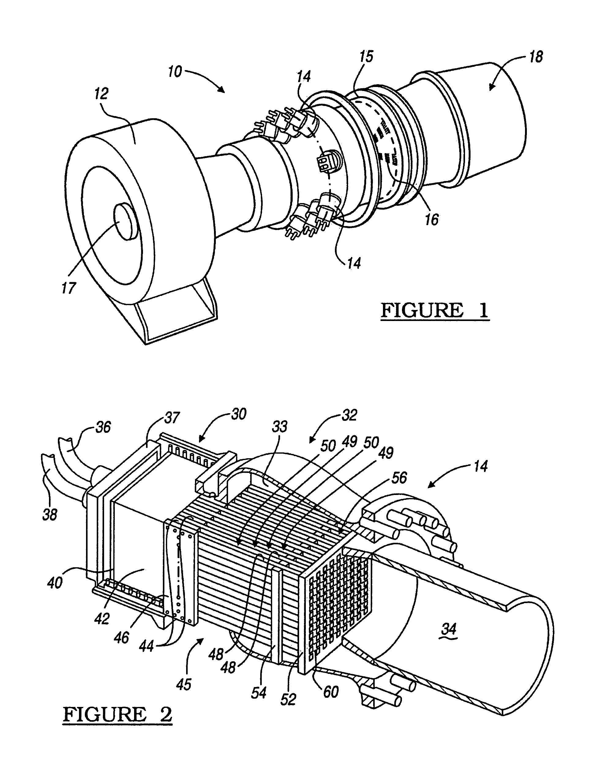
[0028]Referring to FIG. 1, a gas powered turbine 10 in accordance with a preferred embodiment of the present invention is shown. The gas powered turbine 10 may use several different gaseous fuels, such as hydrocarbons (including methane, natural gas, propane, kerosene, and other generally known combustible fuels), hydrogen, SYNTHESIS fuels, and any other appropriate fuel, that are combusted and that expand to move portions of the gas powered turbine 10 to produce power. An important component of the gas powered turbine 10 is a compressor 12 which forces atmospheric air into the gas powered...


PUM


Abstract

A combustor assembly including an injector element able to inject and substantially mix a fuel with a vitiated air stream, so that the substantially all of the fuel injected into the vitiated air stream reaches an auto ignition temperature before it combusts. Generally, the injector element expels the fuel from the injector orifice at a rate, a velocity, a trajectory, or a flow geometry able to mix the fuel with the vitiated air. Generally, the fuel is able to mix with the vitiated air in such a manner that the fuel is substantially mixed and no substantially high or substantially low concentrations of fuel exist in the air stream at the time that the fuel reaches the auto ignition temperature.

Description

FIELD OF THE INVENTION[0001]The present invention relates generally to gas powered turbines for generating power, and more particularly to a low nitrous oxide emission combustion system for gas powered turbine systems.BACKGROUND OF THE INVENTION[0002]It is generally known in the art to power turbines with gases being expelled from combustion chambers. These gas powered turbines can produce power for many applications such as terrestrial power plants. In the gas powered turbine a fuel, such as a hydrocarbon (for example methane or kerosene) or hydrogen, is combusted in an oxygen rich environment. Generally, these combustion systems have high emissions of undesirable compounds such as nitrous oxide compounds (NOX) and carbon containing compounds. It is generally desirable to decrease these emissions as much as possible so that undesirable compounds do not enter the atmosphere. In particular, it has become desirable to reduce NOX emissions to a substantially low amount. Emissions of NO...

Claims


Application Information

Patent Timeline
Patent Type & Authority Patents(United States)
IPC IPC(8): F01C1/00F02G3/00F23C9/00F23R3/28
CPCF23C9/00F23R3/286F23C2900/99001Y02E20/342Y02E20/34
Inventor FARHANGI, SHAHRAM
Owner THE BOEING CO
Why Eureka
Try Eureka