
Combined funnel kit and fluid collection device

a funnel kit and fluid collection technology, applied in the field of funnel kits, can solve the problems of excessive time-consuming methods, viscous substances such as motor oil, that require an extremely extended period of time to adequately drain residue, etc., and achieve the effect of preventing fluid from exiting the passageway

Inactive Publication Date: 2008-12-30
BOWER DOUGLAS M
View PDF15 Cites 8 Cited by
  • Summary
  • Abstract
  • Description
  • Claims
  • Application Information

AI Technical Summary

Benefits of technology

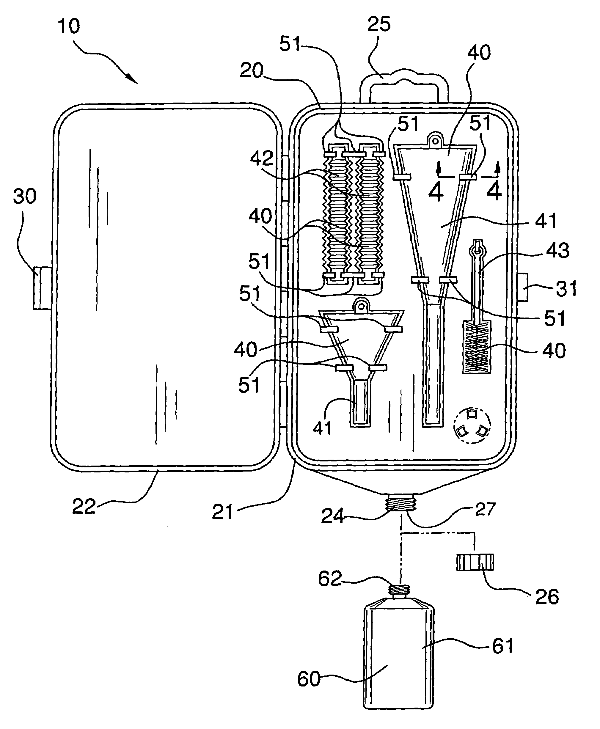
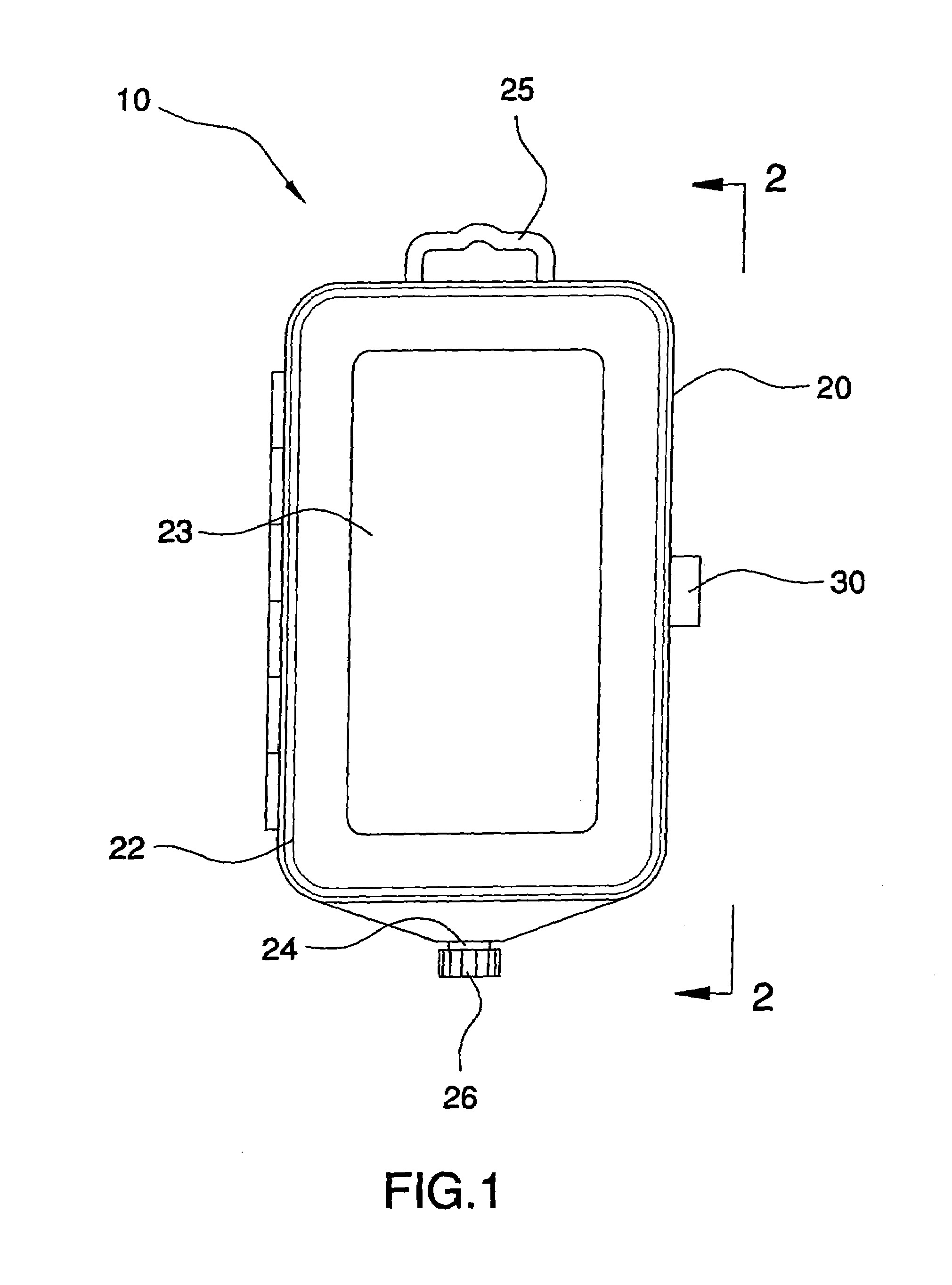
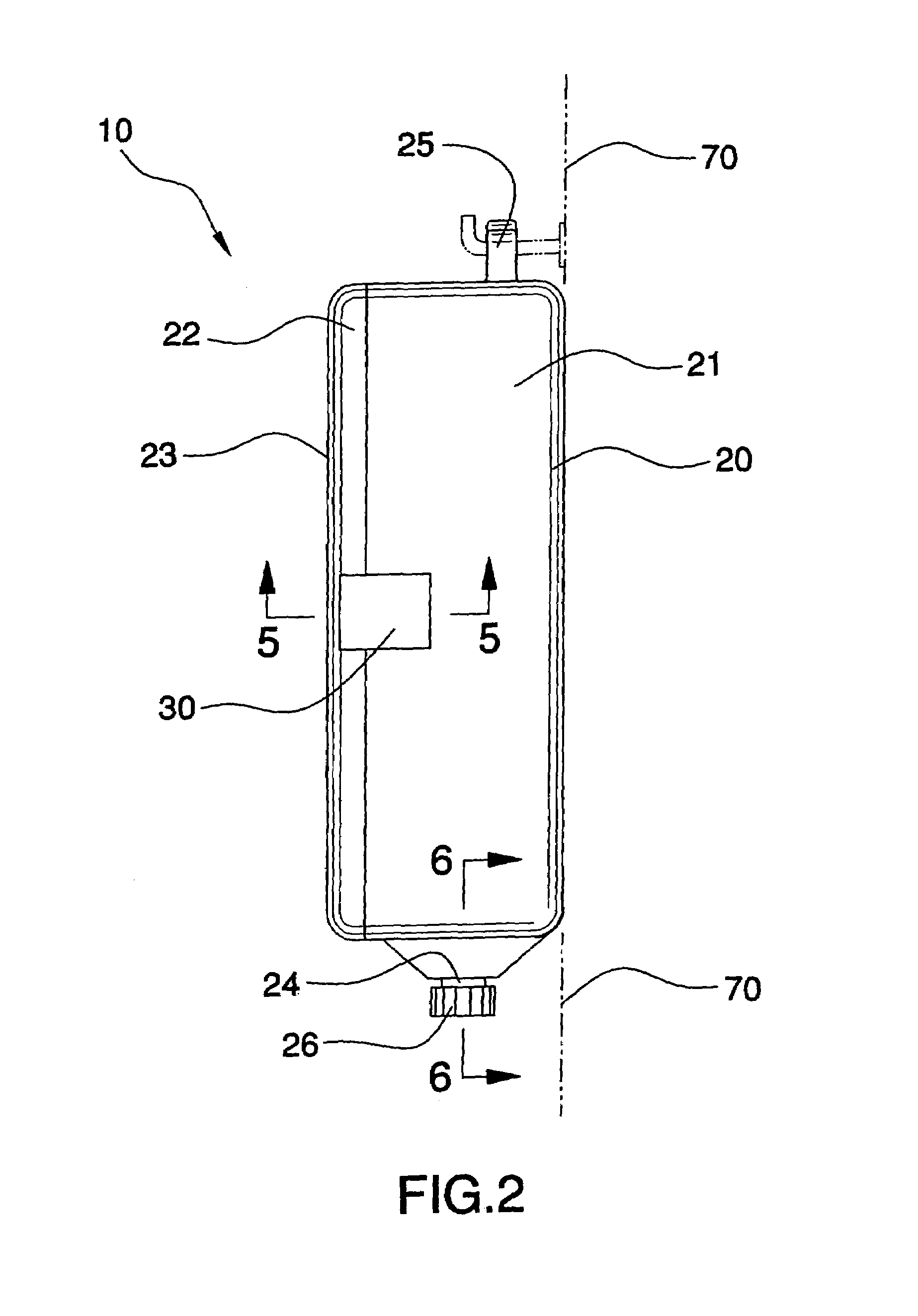
[0013]The housing further has an outlet formed subjacent to the plurality of depressions that defines a passageway for advantageously directing fluid outwardly from the housing when the kit is disposed along a vertical plane. The housing conveniently includes a handle extending upwardly from the base section for allowing a user to effectively hang the kit at an elevated position.
[0016]The device also includes an end cap threadably securable to the outlet for effectively preventing fluid from exiting the passageway. Advantageously, any conventional 1 quart bottle of motor oil, hereinafter referred to as collecting apparatus, may be threadably secured to the outlet for collecting fluid traveling downwardly from the housing. The collecting apparatus is removably securable to the outlet when the end cap is removed therefrom. Such an apparatus preferably includes a reservoir (vessel) that has a threaded top opening, such as conventional motor oil bottles, wherein the outlet has a threaded inner surface for securely receiving the apparatus thereat.

Problems solved by technology

Individuals have discovered that viscous substances, such as motor oil, normally require an extremely extended period of time to adequately drain the residue from the funnel which was used to deliver the particular substance.
Additionally, since some vehicles require four, five, or even six quarts of oil, this method can be extremely time consuming.

Method used


Image

  • Combined funnel kit and fluid collection device
  • Combined funnel kit and fluid collection device
  • Combined funnel kit and fluid collection device

Examples


Embodiment Construction

[0025]The present invention will now be described more fully hereinafter with reference to the accompanying drawings, in which a preferred embodiment of the invention is shown. This invention may, however, be embodied in many different forms and should not be construed as limited to the embodiment set forth herein. Rather, this embodiment is provided so that this application will be thorough and complete, and will fully convey the true scope of the invention to those skilled in the art. Like numbers refer to like elements throughout the figures.

[0026]The device of this invention is referred to generally in FIGS. 1-6 by the reference numeral 10 and is intended to provide a combined funnel kit and fluid collection device. It should be understood that the device 10 may be used to drain many different types of fluid and should not be limited to only motor oil.

[0027]Referring initially to FIG. 1, the device 10 includes a housing 20 that has a base section 21, a lid section 22 and a subst...


PUM

PropertyMeasurementUnit
Volumeaaaaaaaaaa

Abstract

An automotive kit for catching oil drippings includes a housing having a base section and a lid section pivotally connected therewith, an outlet formed within the housing for defining a passageway to advantageously direct fluid outwardly from the housing when the kit is disposed along a vertical plane. The present invention further includes a plurality of automotive accessories, and a mechanism for advantageously maintaining the accessories at a substantially stable position when positioned within the housing. An end cap is securable to the outlet for preventing fluid from exiting the passageway, and a reservoir is connectable to the outlet for collecting fluid traveling downwardly from the housing. A conventional 1 quart bottle of oil may be attached to the housing outlet for collecting oil drippings wherein the outlet includes a lip portion for directing the oil drippings towards the center thereof.

Description

CROSS REFERENCE TO RELATED APPLICATIONS[0001]Not Applicable.STATEMENT REGARDING FEDERALLY SPONSORED RESEARCH OR DEVELOPMENT[0002]Not Applicable.REFERENCE TO A MICROFICHE APPENDIX[0003]Not Applicable.BACKGROUND OF THE INVENTION[0004]1. Technical Field[0005]This invention relates to a funnel kit and, more particularly, to a combined funnel kit and fluid collection device for use in various industries.[0006]2. Prior Art[0007]The use of funnels is known in the prior art. More specifically, funnels heretofore devised and utilized for the purpose of draining single containers of fluid within various ports of a vehicle are known to consist basically of familiar, expected and obvious structural configurations, notwithstanding the myriad of designs encompassed by the crowded prior art which have been developed for the fulfillment of countless objectives and requirements.[0008]Individuals have discovered that viscous substances, such as motor oil, normally require an extremely extended period...

Claims


Application Information

Patent Timeline
IPC IPC(8): B65D69/00B65B1/04
CPCF16N31/002
Inventor BOWER, DOUGLAS M.
Owner BOWER DOUGLAS M
Learn More