Drain assembly for a bathtub and the like

a technology for draining parts and bathtubs, which is applied in water installation, construction, domestic plumbing, etc., can solve the problems of cumbersome and difficult traditional installation methods, leakage, and difficult testing of traditional draining assemblies

Inactive Publication Date: 2013-12-26
WCM IND INC
View PDF1 Cites 15 Cited by
  • Summary
  • Abstract
  • Description
  • Claims
  • Application Information

AI Technical Summary

Benefits of technology

[0012]It is another aspect of the present invention to provide a drain assembly adapted for interconnection to a tub having a drain port formed in a bottom wall, the drain port having a diameter, the drain assembly comprising: a drain pipe including a first portion, a second portion, and an elbow portion positioned between, and integrally connecting, the first portion and the second portion, the first portion including an annular flange and a threaded portion positioned between the annular flange and the elbow portion, wherein the threaded portion, the elbow portion, and the second portion have a maximum diameter that is less than the diameter of the drain port, and wherein the annular flange has a maximum diameter that is larger than the diameter of the drain port; and a nut configured to threadably engage the threaded portion of the drain pipe to secure the drain pipe to the bottom wall of the tub.
[0013]It is still yet another aspect of the present invention to provide a drain elbow adapted for interconnection to a tub having a drain port formed in a bottom wall, the drain port having a diameter, the drain elbow comprising: a first portion including an annular flange and an externally threaded portion, the annular flange having a maximum diameter that is larger than the diameter of the drain port; a second portion; and an elbow portion positioned between, and integrally connecting, the first portion and the second portion, wherein the externally threaded portion is positioned between the annular flange and the elbow portion, and wherein the externally threaded portion, the elbow portion, and the second portion have a maximum diameter that is less than the diameter of the drain port.

Problems solved by technology

The traditional installation method is cumbersome and difficult as it requires multiple components to be held in place during assembly.
In addition, traditional drain assemblies are difficult to test.
After a predetermined amount of time, leaks will be apparent if the water level in the vent pipe falls.
Because of risk of damage, plumbers prefer not to use the final closure valve, i.e. stopper, to block the drain.

Method used


Image

  • Drain assembly for a bathtub and the like
  • Drain assembly for a bathtub and the like
  • Drain assembly for a bathtub and the like

Examples


Embodiment Construction

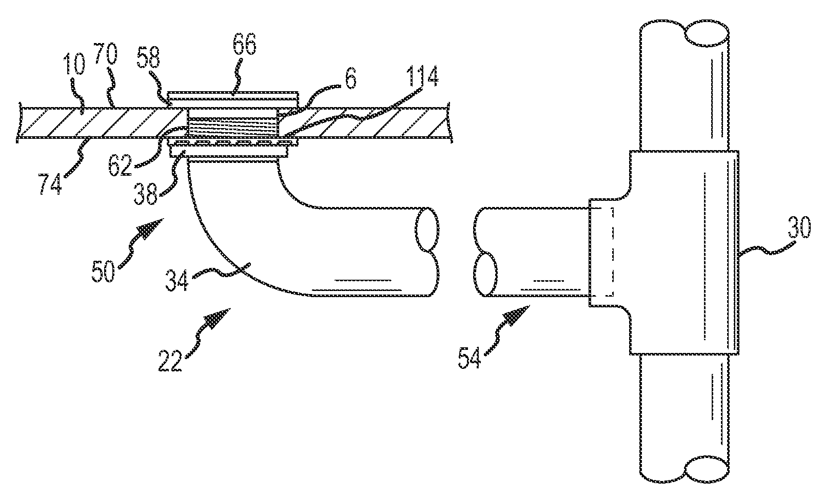
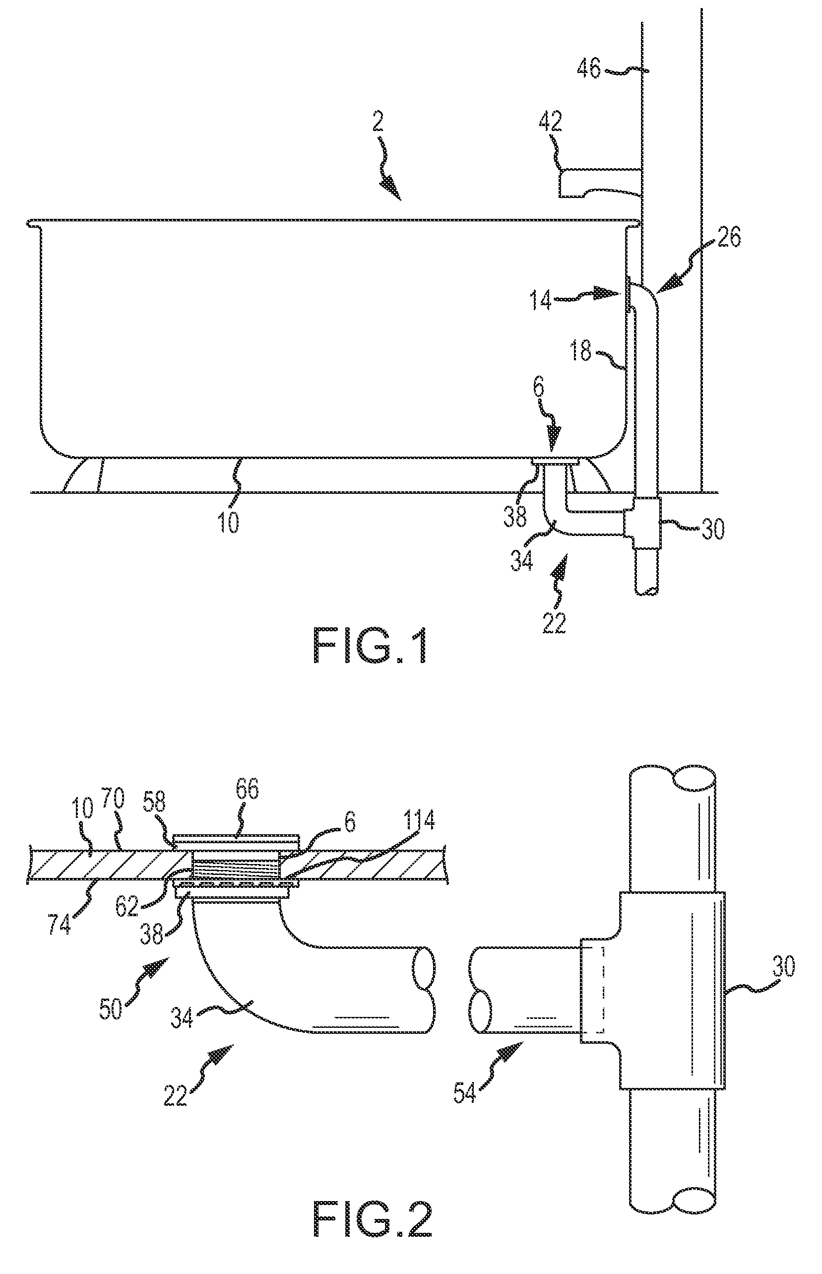
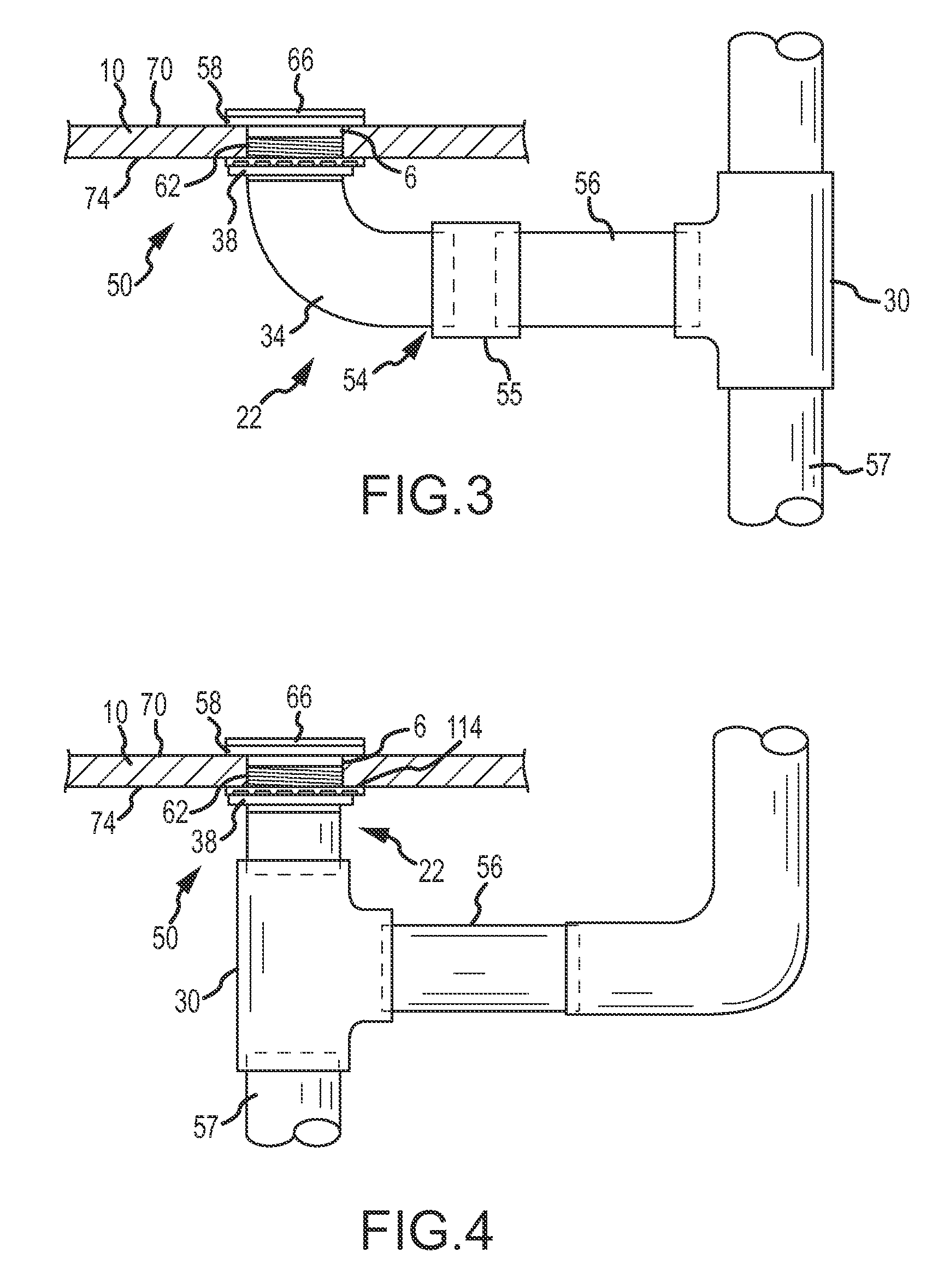
[0050]Referring to FIGS. 1-11, a bathtub 2 includes a drain port 6 provided in a bottom wall 10 and an overflow port 14 provided in a sidewall 18. A drain assembly 22 is interconnected to the bottom wall 10 and associated with the drain port 6, and an overflow assembly 26 is interconnected to the sidewall 18 and associated with the overflow port 14. A tee connector 30 interconnects the drain assembly 22 and the overflow assembly 26. The drain assembly 22 includes a drain pipe 34, which may be generally L-shaped, that is attached to the bathtub 2 with a nut 38. The drain pipe 34 has a first end 50 associated with the bottom wall 10 of the bathtub 2, and a second end 54 that is interconnected to the tee connector 30. The first end 50 includes an annular flange 58 and an externally-threaded portion 62. A membrane 66 may be interconnected to the first end 50 of the drain pipe 34 to assist in leak testing.

[0051]The drain pipe 34 is interconnected to the bathtub 2 by first inserting the s...


PUM


Abstract

A drain assembly including a drain pipe with a threaded portion and a nut is provided. The drain pipe includes a first end, an elbow portion, and a second end. The first end includes an annular flange and the threaded portion. To interconnect the drain assembly to a bathtub, the second end of the drain pipe is inserted through a drain port of the tub until the annular flange abuts a bottom wall of the tub. The nut is then threaded onto the threaded portion of the drain pipe to secure the drain pipe to the bathtub. The second end of the drain pipe is then interconnected to drain plumbing.

Description

CROSS REFERENCE TO RELATED APPLICATIONS[0001]This application is a continuation-in-part of U.S. patent application Ser. No. 13 / 726,840, filed Dec. 26, 2012, which is a continuation-in-part of U.S. patent application Ser. No. 13 / 461,422, filed May 1, 2012, now U.S. Pat. No. 8,505,132, which is a continuation-in-part of U.S. patent application Ser. No. 12 / 057,660, filed Mar. 28, 2008, now U.S. Pat. No. 8,166,584, which is a continuation-in-part of U.S. patent application Ser. No. 10 / 732,726, filed Dec. 10, 2003, now U.S. Pat. No. 8,302,220, which is a continuation-in-part of U.S. patent application Ser. No. 09 / 954,420, filed Sep. 17, 2001, now U.S. Pat. No. 6,691,411. The entire disclosures of the above-referenced patents and applications are incorporated by reference herein.BACKGROUND OF THE INVENTION[0002]The traditional method of interconnecting a drain and associated plumbing to a bathtub generally comprises engaging a flange associated with the drain pipe to the bottom surface of...

Claims


Application Information

Patent Timeline
Patent Type & Authority Applications(United States)
IPC IPC(8): E03C1/20
CPCE03C1/20E03C1/22E03C1/2306
Inventor BALL, WILLIAM T.PILARCZYK, ERIC
Owner WCM IND INC
Why Eureka
Try Eureka