Step-by-step variable transmission

a transmission and step-by-step technology, applied in the direction of transmission elements, belts/chains/gearings, toothed gearings, etc., can solve the problems of comparatively high torque loading at the countershaft and comparatively difficult mounting of the drive output, and achieve the effect of short installation length

Active Publication Date: 2009-01-06
GETRAG GETRIEBE & ZAHNRADFABRIK HERMANN HAGENMEYER GMBH & CO KG
View PDF16 Cites 36 Cited by
  • Summary
  • Abstract
  • Description
  • Claims
  • Application Information

AI Technical Summary

Benefits of technology

[0015]This measure results in the drive output shaft being mounted with a favourable contact pattern. It is therefore also possible to obtain very stiff mounting of the drive output constant gearwheel set, in particular substantially without installation length disadvantages. There is generally also a resulting considerably more favourable bearing loading. Here, the bearings can be arranged further away from the drive output constant gearwheel set.
[0047]resulting lower inertias, as a result of which it is possible to realize short shift times and / or smaller-dimensioned shift clutches or synchronous clutches.

Problems solved by technology

This leads to a comparatively high torque loading at the countershaft.
One problem of step-by-step variable transmissions with a drive output constant gearwheel set is that it is comparatively difficult to mount the drive output constant gearwheel set in such a stiff manner that it still has an acceptable contact pattern despite its comparatively large width.

Method used


Image

  • Step-by-step variable transmission
  • Step-by-step variable transmission
  • Step-by-step variable transmission

Examples


Embodiment Construction

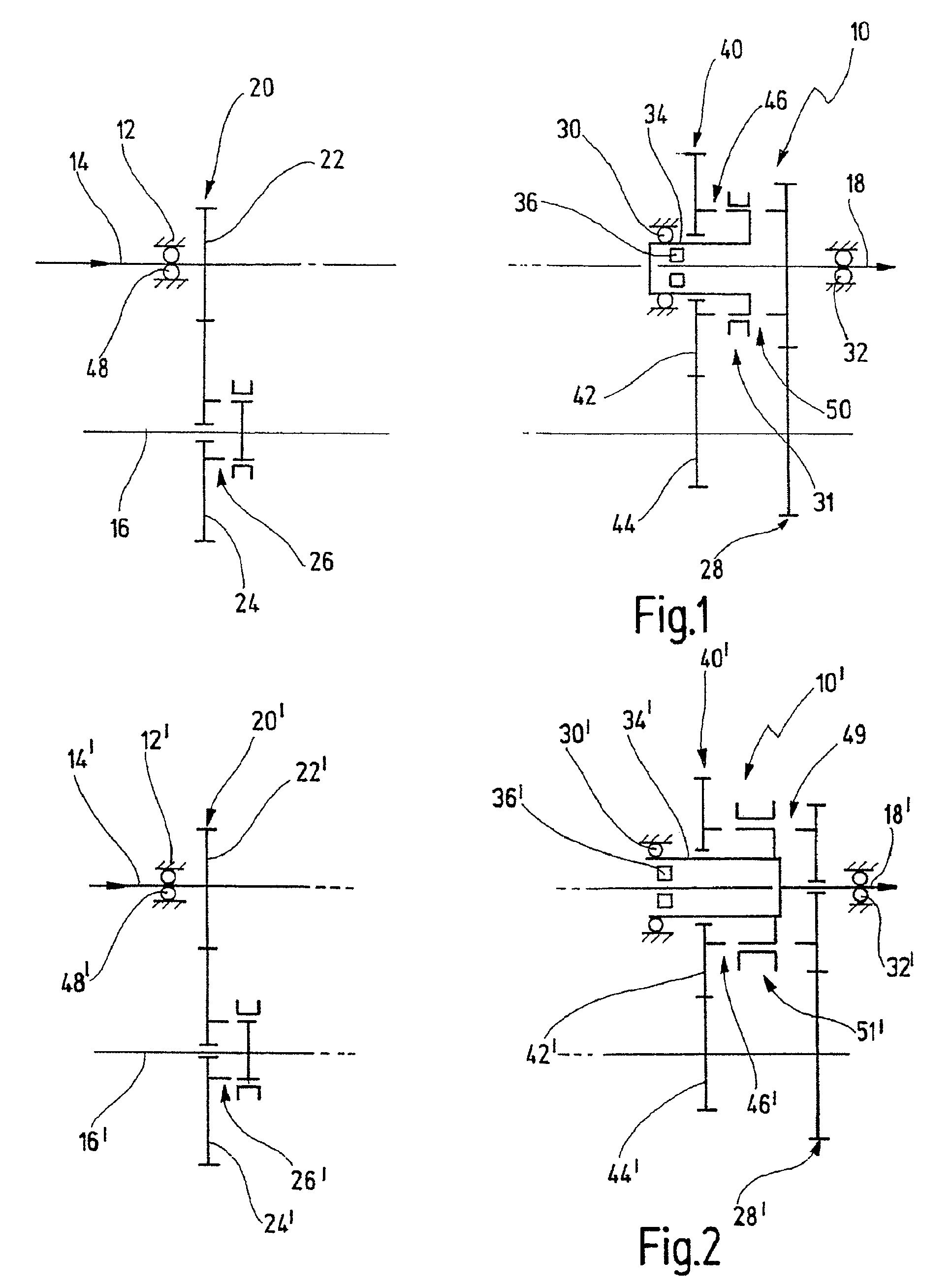
[0056]In FIG. 1, a first embodiment of the step-by-step variable transmission according to the invention is denoted overall by 10.

[0057]The step-by-step variable transmission 10 is designed as an in-line transmission, that is to say as a transmission for longitudinal installation in a motor vehicle, in particular a passenger vehicle.

[0058]The step-by-step variable transmission 10 has a housing 12 which is generally designed as a multi-part housing. For the purposes of a simplified illustration, the housing 12 in the illustration of FIG. 1—and in the following illustrations—is illustrated in an undivided state. The housing 12 can be a housing which serves merely to hold functionally essential parts of the step-by-step variable transmission. The housing 12 can however also be formed as part of adjacent housings and for example comprise a partition between the gearwheel sets of the step-by-step variable transmission 10 and / or to an input-side starting and separating clutch or the like....


PUM


Abstract

A step-by-step variable transmission has a housing, a drive input shaft device, a drive output shaft and a countershaft. A plurality of gearwheel sets are mounted on the drive input shaft and on the countershaft. The gearwheel sets can be shifted so as to establish different gear stages by means of respective shift clutches. The countershaft is connected to the drive output shaft by means of a drive output constant wheel set. The drive output shaft is rotatably mounted in the region of its opposite ends on the housing by means of two bearings. At least one of the gearwheel sets is mounted in the region in the axial direction between the two bearings of the drive output shaft.

Description

CROSS-REFERENCE TO RELATED APPLICATIONS[0001]This is a Continuation application of International patent application PCT / 2005 / 013378, filed Dec. 12, 2005, which claims the priority of German patent application DE 10 2005 005 338, filed Jan. 27, 2005.BACKGROUND OF THE INVENTION[0002]The present invention relates to a step-by-step variable transmission, in particular for motor vehicles, having a housing, having a drive input shaft device, having a drive output shaft and having a countershaft, with a plurality of gearwheel sets being mounted on the drive input shaft and on the countershaft, with it being possible for the gearwheel sets to be shifted so as to establish different gear stages by means of respective shift clutches, with the countershaft being connected to the drive output shaft by means of a drive output constant gearwheel set, and with the drive output shaft being rotatably mounted in the region of its opposite ends on the housing by means of two bearings.[0003]A step-by-s...

Claims


Application Information

Patent Timeline
Patent Type & Authority Patents(United States)
IPC IPC(8): F16H3/24
CPCF16H3/006F16H3/0915Y10T74/19288Y10T74/19233Y10T74/194F16H2200/0052
Inventor NICKLASS, OLIVER
Owner GETRAG GETRIEBE & ZAHNRADFABRIK HERMANN HAGENMEYER GMBH & CO KG
Why Eureka
Try Eureka