
Rotational hinge assembly for a knee brace having an osteoarthritis treatment function

a knee brace and rotational technology, applied in the field of orthopaedic braces, can solve problems such as pain in the joint and chronic pain of the subj

Active Publication Date: 2009-02-03
BREG
View PDF25 Cites 51 Cited by
  • Summary
  • Abstract
  • Description
  • Claims
  • Application Information

AI Technical Summary

Benefits of technology

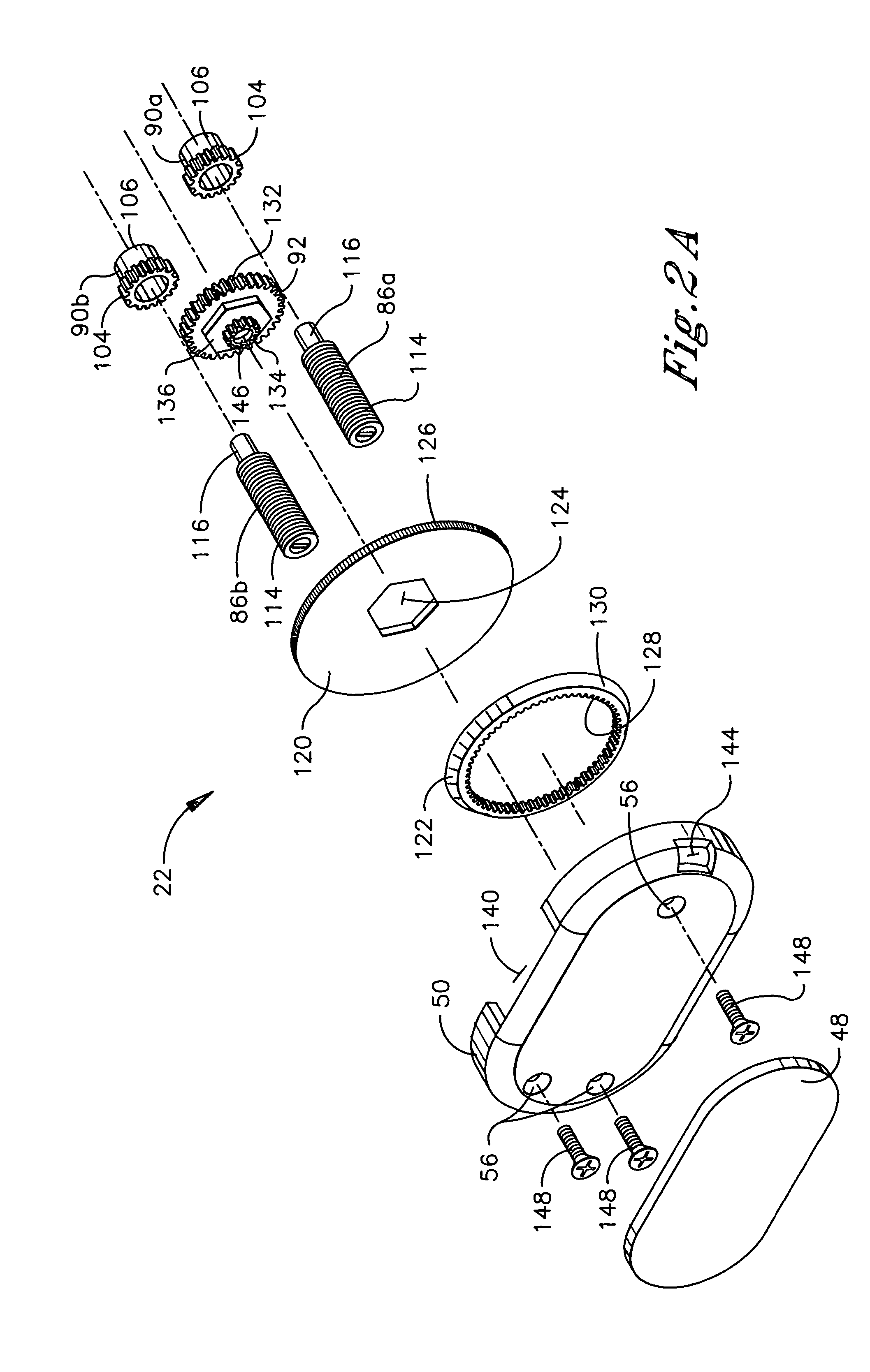
[0009]The first and second adjustment screws are connected to the condyle engagement member, thereby enabling proximal displacement of the condyle engagement member in response to outward telescoping of the first and second adjustment screws and enabling distal displacement of the condyle engagement member in response to inward telescoping of the first and second adjustment screws.

Problems solved by technology

One destabilizing condition of the knee joint is osteoarthritis, a degenerative disease that results in chronic pain to the subject when the knee joint is statically or dynamically loaded.
Osteoarthritic pain is caused by an unbalanced loading on the medial or lateral compartment of the knee joint which closes the clearance space forming the compartment between the condyles of the femur and tibia.
When there is contact of the condyles in the afflicted compartment of the knee joint, abrasion occurs at the contact surface producing pain in the joint.

Method used


Image

  • Rotational hinge assembly for a knee brace having an osteoarthritis treatment function
  • Rotational hinge assembly for a knee brace having an osteoarthritis treatment function
  • Rotational hinge assembly for a knee brace having an osteoarthritis treatment function

Examples


Embodiment Construction

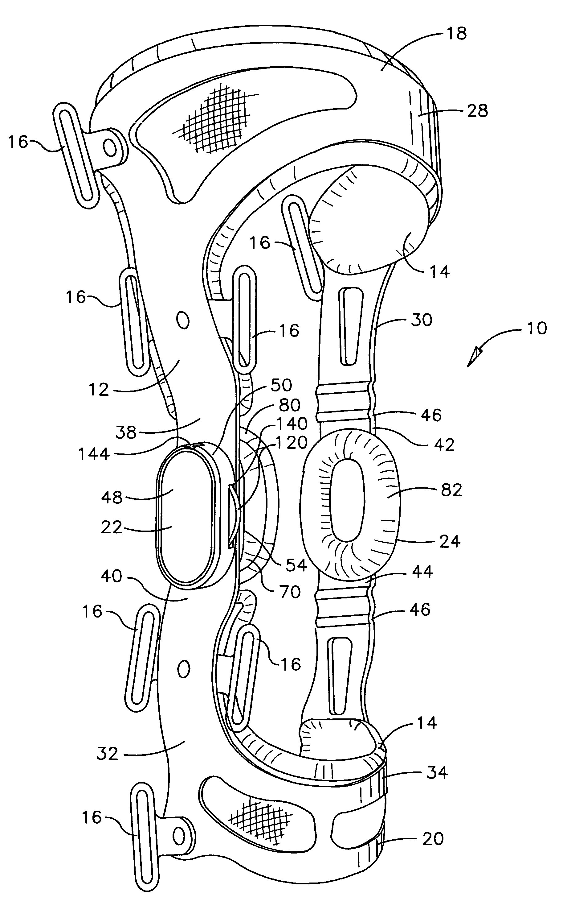
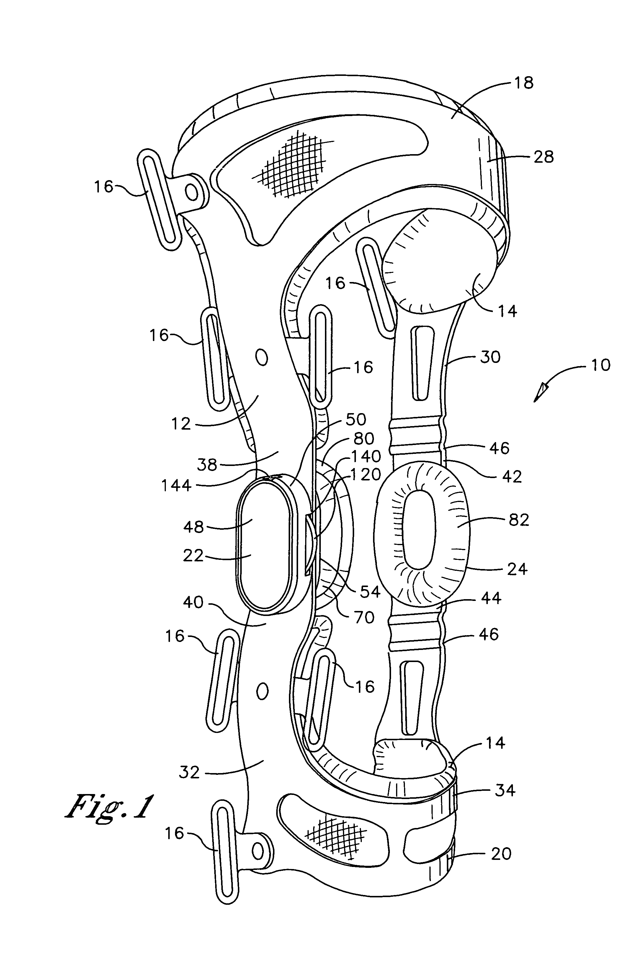
[0019]There are a number of relative terms defined below which are used in the following description to distinguish various elements of a rotationally-hinged knee brace from one another, but which are not to be construed as limiting the scope of the present invention. The relative terms “medial” and “lateral” describe the relative proximity of certain elements to the central longitudinal axis of the body of the user when the knee brace is secured to a leg of the user. A “medial” element is closer to the central longitudinal axis of the body, while a “lateral” element is further from the central longitudinal axis of the body.

[0020]The terms “proximal” and “distal” describe the relative proximity of certain elements to the knee joint when the knee brace is secured to the leg of the user. A “proximal” element is closer to the knee joint, while a “distal” element is further from the knee joint. The terms “upper” and “lower” describe the position of certain elements as being either above...


PUM


Abstract

A hinge assembly for a knee brace includes a screw seat, a screw seat gear, an adjustment screw, a condyle engagement member, and an adjustment actuator gear. The screw seat has a bore with an internal thread. The screw seat gear is positioned at an end of the screw seat and the screw seat rotates in response to rotation of the screw seat gear. The adjustment actuator gear engages the screw seat gear and the screw seat gear rotates in response to rotation of the adjustment actuator gear. The adjustment screw has an external thread that is threaded into the internal thread of the screw seat, thereby enabling outward or inward telescoping of the adjustment screw within the bore in response to rotation of the adjustment actuator gear. The adjustment screw is connected to the condyle engagement member, thereby enabling proximal displacement of the condyle engagement member in response to outward telescoping of the adjustment screw and enabling distal displacement of the condyle engagement member in response to inward telescoping of the adjustment screw.

Description

TECHNICAL FIELD[0001]The present invention relates generally to orthopedic braces, and more particularly to a knee brace having a rotational hinge assembly configured to enable treatment of osteoarthritis.BACKGROUND OF THE INVENTION[0002]Orthopedic braces embody a broad range of structures, each having the common purpose of supporting and / or stabilizing a skeletal joint when worn on the body of a user. The orthopedic brace may serve either a preventative role or a remedial role. In a preventative role, the brace provides added support and stability to a healthy skeletal joint, thereby reducing the risk of injury when the joint is subjected to undue stress. In a remedial role, the brace supports and stabilizes a skeletal joint which has been weakened by injury or other infirmity, thereby reinforcing the joint and reducing the risk of further injury while the joint is rehabilitated.[0003]Conventional orthopedic braces typically include a frame consisting of a plurality of rigid suppor...

Claims


Application Information

Patent Timeline
Patent Type & Authority Patents(United States)
IPC IPC(8): A61F5/00A61F5/37A61F13/00A61B19/00
CPCA61F5/0123A61F2005/0139A61F2005/0165A61F2005/0174
Inventor MASON, BRADLEY R.AL-JADDA, AADEL
Owner BREG
Learn More