Energy recovering apparatus and method and method of driving plasma display panel using the same

Inactive Publication Date: 2009-02-03
LG ELECTRONICS INC
View PDF19 Cites 1 Cited by
  • Summary
  • Abstract
  • Description
  • Claims
  • Application Information

AI Technical Summary

Benefits of technology

[0028]Accordingly, it is an object of the present invention to provide an energy recovering apparatus and method and a method of driving a plasma display panel using the same that are adaptive for improving light-emission efficiency.

Problems solved by technology

However, an application of the rectangular waveform during the sustain period raises a problem of a low light-emission efficiency.
Herein, since an amount of a generated light is in proportion to a discharge time (or period), the conventional PDP has a low light-emission efficiency.
However, the energy recovering apparatus as shown in FIG. 5 has a drawback in that, since it uses a ramp pulse, power consumption is wasted.
More specifically, a ramp pulse rising slowly at a predetermined slope is generated by utilizing a resistor R. Accordingly, another conventional embodiment raises a problem in that an additional power consumption is wasted due to the resistor R.

Method used


Image

  • Energy recovering apparatus and method and method of driving plasma display panel using the same
  • Energy recovering apparatus and method and method of driving plasma display panel using the same
  • Energy recovering apparatus and method and method of driving plasma display panel using the same

Examples


Embodiment Construction

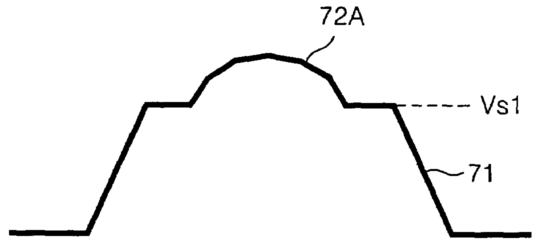
[0055]FIG. 6 is a circuit diagram representing an energy recovering apparatus provided at a scan electrode Y according to an embodiment of the present invention. This energy recovering apparatus also is symmetrically provided at a sustain electrode Z around a panel capacitor Cp. FIG. 7 represents a voltage of the panel capacitor Cp charged and discharged by a waveform supplied from the energy recovering apparatus shown in FIG. 6.

[0056]Referring to FIG. 6 and FIG. 7, the energy recovering apparatus according to the embodiment of the present invention includes a rectangular waveform supplier 32 for supplying a rectangular waveform to one side electrode of the panel capacitor Cp, and a tower waveform supplier 34 for supplying a sinusoidal waveform or a resonant waveform at a peak voltage of the rectangular waveform.

[0057]The panel capacitor Cp is to equivalently express a capacitance formed between the scan electrode Y and the sustain electrode Z.

[0058]The rectangular waveform supplier...


PUM


Abstract

An energy recovering apparatus for improving light-emission efficiency is disclosed. In the apparatus, a rectangular waveform supplier supplies a rectangular waveform to a panel capacitor. A tower waveform supplier supplies a tower waveform having any one shape of a sinusoidal waveform, a resonant waveform and a ripple waveform to the panel capacitor charged by said rectangular waveform.

Description

[0001]This application claims the benefit of Korean Patent Application No. P2003-37867 filed in Korea on Jun. 12, 2003, which is hereby incorporated by reference.BACKGROUND OF THE INVENTION[0002]1. Field of the Invention[0003]This invention relates to a plasma display panel, and more particularly to an energy recovering apparatus and method and a method of driving a plasma display panel using the same that are adaptive for improving light-emission efficiency.[0004]2. Description of the Related Art[0005]Generally, a plasma display panel (PDP) radiates a phosphorous material using an ultraviolet ray with a wavelength of 147 nm generated upon discharge of an inactive mixture gas such as He+Xe, Ne+Xe or He+Ne+Xe, to thereby display a picture including characters and graphics. Such a PDP is easy to be made into a thin-film and large-dimension type. Moreover, the PDP provides a very improved picture quality owing to a recent technical development. Particularly, since a three-electrode, al...

Claims


Application Information

Patent Timeline
IPC IPC(8): G09G3/28G09G3/2807G09G3/294G09G3/296H02J1/00
CPCG09G3/2942G09G3/296G09G3/2965G09G3/2807
Inventor JUNG, YUN KWON
Owner LG ELECTRONICS INC
Why Eureka
Try Eureka