Plasma display panel

Inactive Publication Date: 2005-10-27
PANASONIC CORP
View PDF0 Cites 1 Cited by
  • Summary
  • Abstract
  • Description
  • Claims
  • Application Information

AI Technical Summary

Benefits of technology

[0017] In the plasma display panel according to the embodiment, the protective layer protecting the dielectric layer facing the interior of the discharge space is formed of a cesium complex oxide, which then makes it possible to reduce the discharge voltage to a level lower than an MgO-made protective layer an

Problems solved by technology

However, cesium being a simple substance has conductivity and lacks the so-called memory effect of accumulating wall charges.
Thus, the simple substance cesium is unsuitable for alternative-current plasma display panel.
Further, the simple substance cesium shows very high activity a

Method used


Image

  • Plasma display panel
  • Plasma display panel
  • Plasma display panel

Examples


Embodiment Construction

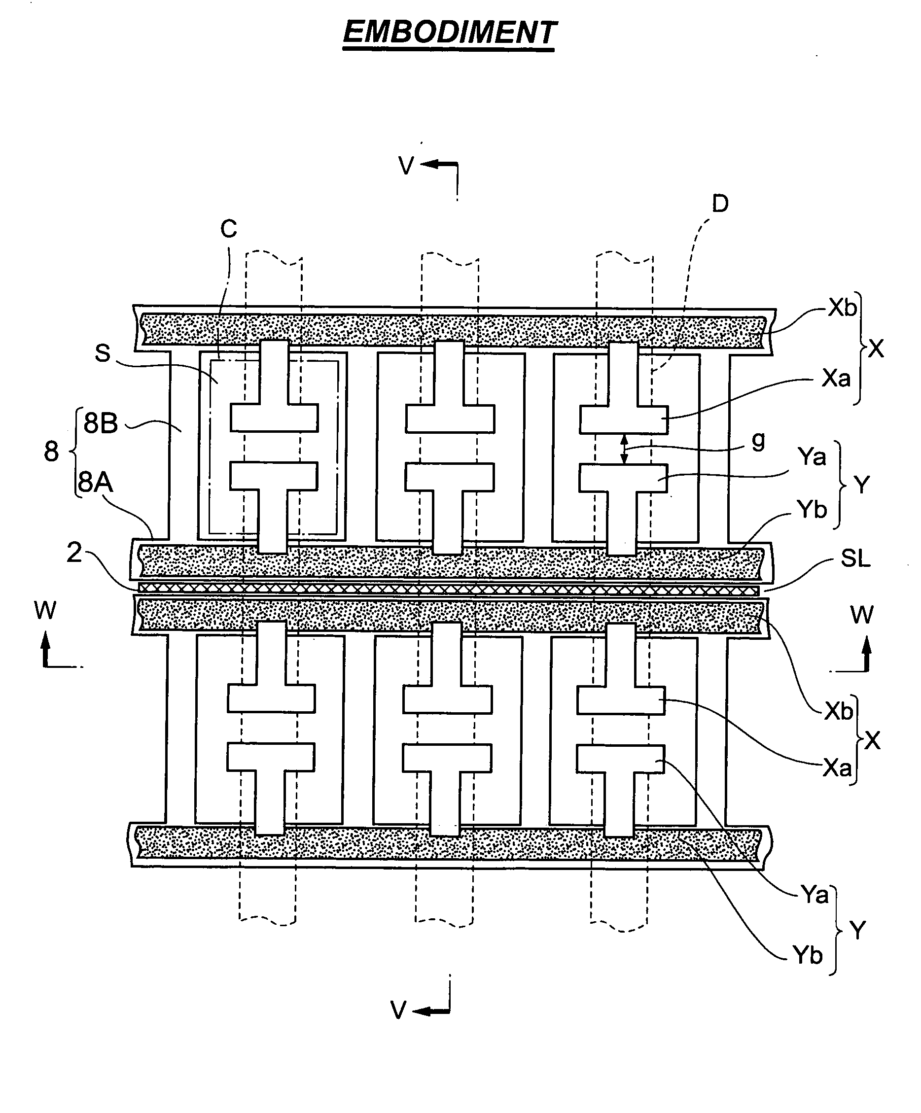
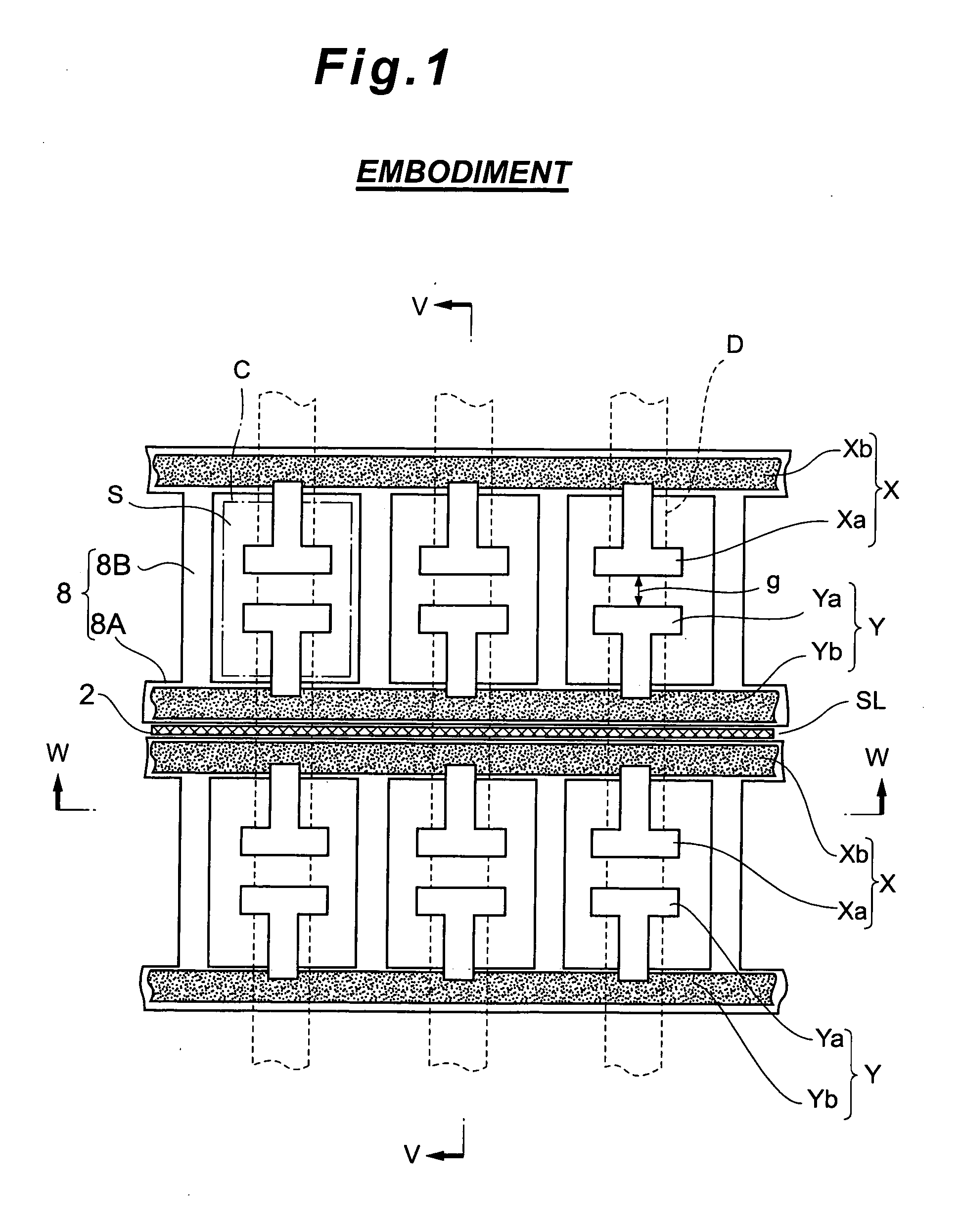
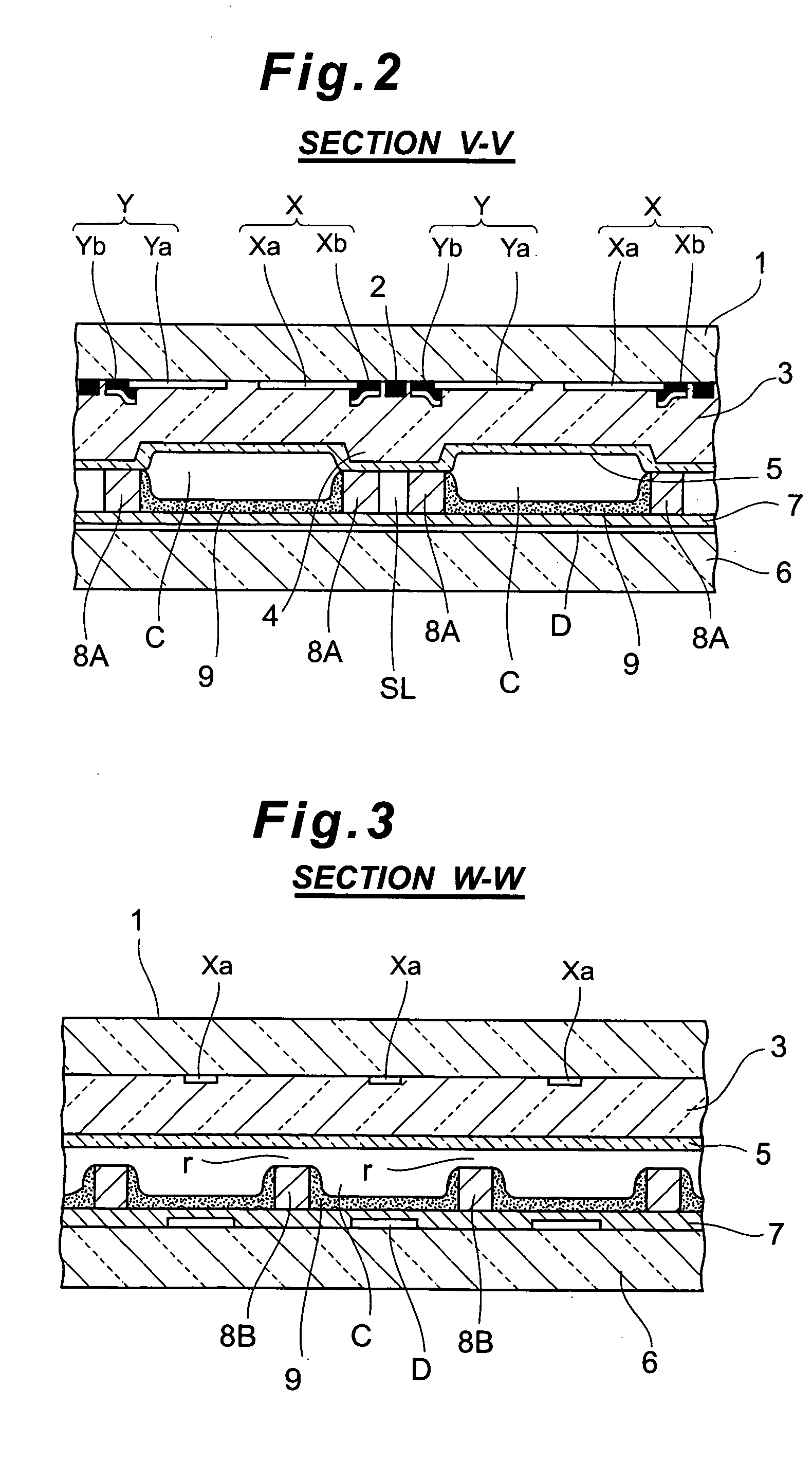
[0023] FIGS. 1 to 3 illustrate an example of the structure of a plasma display panel (hereinafter referred to as “PDP”) subject to application of the present invention. FIG. 1 is a schematic front view of the PDP in the embodiment. FIG. 2 is a sectional view taken along the V-V line in FIG. 1. FIG. 3 is a sectional view taken along the W-W line in FIG. 1.

[0024] The PDP in FIGS. 1 to 3 has a plurality of row electrode pairs (X, Y) extending in a row direction of a front glass substrate 1 (the right-left direction in FIG. 1) and arranged in parallel on the rear-facing face of the front glass substrate 1 serving as the display surface.

[0025] A row electrode X is composed of T-shaped transparent electrodes Xa formed of a transparent conductive film made of ITO or the like, and a bus electrode Xb formed of a metal film. The bus electrode Xb extends in the row direction of the front glass substrate 1. The narrow proximal end (corresponding to the foot of the “T”) of each transparent ele...


PUM


Abstract

A plasma display panel has a pair of substrates placed opposite each other with a discharge space in between, electrodes formed on an inner face of one of the pair of substrates, a dielectric layer covering the electrodes, and a protective layer covering the dielectric layer, a discharge gas filling the discharge space. The protective layer includes a cesium-based complex oxide.

Description

BACKGROUND OF THE INVENTION [0001] 1. Field of the Invention [0002] This invention relates to a structure of plasma display panels. [0003] The present application claims priority from Japanese Application No. 2004-129361, the disclosure of which is incorporated herein by reference. [0004] 2. Description of the Related Art [0005] Some typical display apparatuses include a plasma display panel (hereinafter referred to as “PDP”) having a hermetically sealed discharge space filled with a discharge gas in which discharge is produced for generating an image, for example. [0006] Such a type of display apparatus is conventionally equipped with a high-spattering-resistant protective layer that covers the display-space-facing area of a structural component of the display apparatus for the purpose of preventing the structural component of the display apparatus from being spattered by plasma generated at the time when a discharge is produced in the discharge space. [0007] Materials for forming ...

Claims


Application Information

Patent Timeline
IPC IPC(8): H01J11/10H01J11/12H01J11/22H01J11/24H01J11/26H01J11/34H01J11/36H01J11/38H01J11/40H01J11/44H01J11/50H01J61/44
CPCH01J11/40H01J11/12
Inventor OKADA, TAKERU
Owner PANASONIC CORP
Why Eureka
Try Eureka