Image display apparatus

Inactive Publication Date: 2011-03-31
CANON KK
View PDF17 Cites 0 Cited by
  • Summary
  • Abstract
  • Description
  • Claims
  • Application Information

AI Technical Summary

Benefits of technology

[0010]The present invention has been proposed in view of the foregoing circumstances, and an object of the present invention is to provide an image display apparatus capable of simplifying a driving circuit of a liquid crystal element, attaining both an improvement in light emission efficiency and a reduction in external light reflection, and realizing a cost reduction.
[0012]According to the image display apparatus of the present invention, the optical element is driven in synchronous with the light emission period and the non-light emission period within one frame of the light emitting element. At this point, if the whole area of the image display apparatus simultaneously performs light emission period / non-light emission period in the drive method, the driving circuit of the liquid crystal element can be simplified because the liquid crystal element can also be driven all together throughout the whole area. Therefore, both an improvement in light emission efficiency of the image display apparatus and a reduction in external light reflection can be attained, and the functions can be realized with low cost.

Problems solved by technology

This leads to a decrease in the contrast of the organic EL display, and the visibility is degraded.
However, the configuration has a problem that the light emission of the organic EL element is also reduced by the circular polarizing plate.
In that case, not only the organic EL element, but also the driving circuit of the liquid crystal element becomes complicated, and the cost of the display may be high.

Method used


Image

  • Image display apparatus
  • Image display apparatus
  • Image display apparatus

Examples


first embodiment

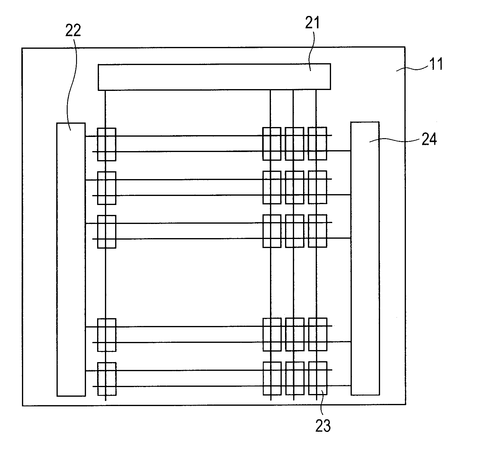
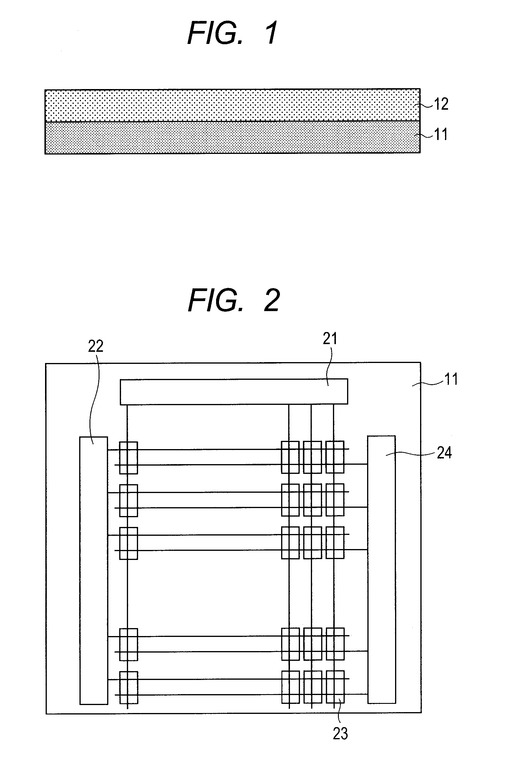
[0064]A schematic configuration of the image display apparatus of a first embodiment is the same as the configuration illustrated in FIG. 1. A summary of the organic EL panel of the first embodiment is the same as the summary illustrated in FIG. 2.

[0065]FIG. 6 illustrates an example of configuration of a pixel circuit including an organic EL element of the first embodiment.

[0066]In FIG. 6, P1 denotes a scanning line, and P2 denotes a light emission period control line. A signal voltage is input from the signal line in accordance with image information. A positive electrode of the organic EL element is connected to a drain terminal of a TFT (M3), and a negative electrode is connected to a ground potential CGND. Hereinafter, a brief operation of the pixel circuit will be described.

[0067]When the signal voltage is written, a signal of HI level is input to the scan signal P1, and a signal of LOW level is input to P2. A transistor M1 is ON, and M3 is OFF. At this point, M3 is not conduct...

second embodiment

[0088]In the first embodiment, the light emission period and the non-light emission period of the organic EL panel 11 are controlled all together throughout all pixels, and the drive of the variable circular polarizing unit 12 is controlled all together throughout the whole area. In a second embodiment, the periods and the drive are controlled row by row.

[0089]The configuration of a pixel circuit of the second embodiment including an image display apparatus, an organic EL panel, and an organic EL element is the same as the configuration of the first embodiment.

[0090]An operation of the entire organic EL panel will be described.

[0091]As in the first embodiment, the organic EL panel of the second embodiment has a matrix arrangement of N rows and M columns. The scanning line P1 connected to the pixel circuit of an n-th row of the organic EL panel is designated with P1n, and the light emission period control line is designated with P2n (N, n, M, and m are natural numbers, 1≦n≦N).

[0092]F...

third embodiment

[0107]In the second embodiment, the light emission period and the non-light emission period of the organic EL panel 11 are controlled row by row, and the drive of the variable circular polarizing unit 12 is also controlled in accordance with the row-by-row control of the organic EL panel 11. In a third embodiment, the periods and the drive are controlled by an arbitrary number of rows. An example of a configuration of controlling two rows by two rows will be illustrated below.

[0108]A configuration of a pixel circuit including an image display apparatus, an organic EL panel, and an organic EL element of the third embodiment is the same as that of the first embodiment.

[0109]An operation of the entire organic EL panel will be described.

[0110]As in the first embodiment, the organic EL panel of the third embodiment has a matrix arrangement of N rows and M columns, the scanning line P1 connected to the pixel circuit of an n-th row of the organic EL panel is designated with P1n, and the li...


PUM


Abstract

A driving circuit of a liquid crystal element is simplified, both an improvement in light emission efficiency and a reduction in external light reflection are attained, and a cost reduction is realized.

Description

BACKGROUND OF THE INVENTION[0001]1. Field of the Invention[0002]The present invention relates to an image display apparatus, and relates, in particular, to a light emitting image display apparatus, such as an organic EL display apparatus, having a reflection electrode.[0003]2. Description of the Related Art[0004]In recent years, an organic EL display using an organic electroluminescence element (hereinafter, called “organic EL element”) is focusing attention. In a typical organic EL element, an organic layer including a light emission layer with about several hundred nm thickness is placed between a reflection electrode and a light transmitting electrode. In such a configuration of element, the reflection electrode reflects light (external light) incident from an outside into the element regardless of light emission by the element. Therefore, under the environment with intense external light, external light reflection components are greater than light emission components of the elem...

Claims


Application Information

Patent Timeline
IPC IPC(8): G02F1/1335H01J1/02H01L27/32
CPCG02F1/13G02F2203/62G09G3/3233H01L51/5281G09G2300/0861G09G2320/02G09G2320/064G09G2300/0842H10K59/8791H10K50/86
Inventor SHIKINA, NORIYUKIISOBE, RYUICHIRO
Owner CANON KK
Why Eureka
Try Eureka