
Lamp unit of vehicle headlamp

a technology for headlamps and lamps, which is applied in the direction of lighting and heating apparatus, light source combinations, lighting support devices, etc., can solve the problems of large size of vehicle headlamps, large size of the unit itself, and large size of the headlamps, and achieve the effect of simplifying the lamp

Inactive Publication Date: 2009-03-10
KOITO MFG CO LTD
View PDF8 Cites 16 Cited by
  • Summary
  • Abstract
  • Description
  • Claims
  • Application Information

AI Technical Summary

Benefits of technology

This configuration enables the downsizing and simplification of the lamp unit while maintaining a sufficiently bright and uniform light distribution, suitable for both low and high beam modes, by utilizing the second light emitting elements to create additional light distribution patterns that complement the basic pattern.

Problems solved by technology

However, according to the constitution described in “Patent Reference 1,” there exists a problem that the vehicle headlamp is large-sized by arranging the number of lamp units.
On the other hand, according to the constitution described in “Patent Reference 2”, there exists a problem that the lamp unit itself is large-sized by arranging the plurality of sets of light emitting elements and reflectors for the single projecting lens and, as a result, the vehicle headlamp is also large-sized.
Further, when such a lamp constitution is adopted, the lamp constitution is rather complicated.

Method used


Image

  • Lamp unit of vehicle headlamp
  • Lamp unit of vehicle headlamp
  • Lamp unit of vehicle headlamp

Examples


Embodiment Construction

[0054]An explanation will be given of an embodiment of the invention in reference to the drawings as follows.

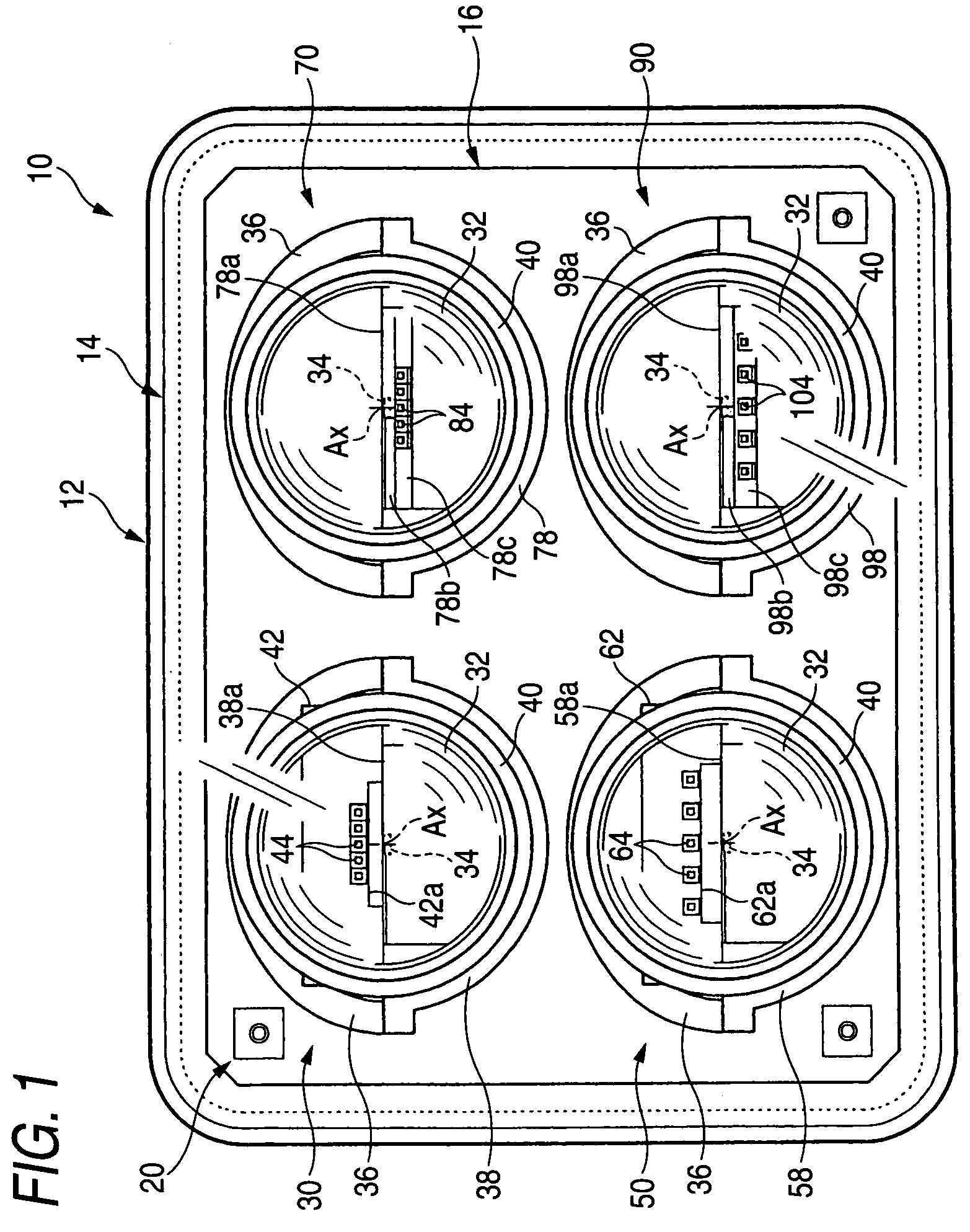
[0055]FIG. 1 is a front view showing a vehicle head lamp 10 according to an embodiment of the invention.

[0056]The vehicle headlamp 10 according to the embodiment shown is constructed by a constitution of containing four of lamp units 30, 50, 70, 90 at inside of a lamp chamber including a lamp body 12 and a transparent cover 14 in a light transmitting state attached to an opening portion of a front end of the lamp body 12.

[0057]All of the four lamp units 30, 50, 70, 90 are lamp units of a projector type and are fixedly supported by a common metal made bracket 16 in two upper and lower stages arrangement.

[0058]The metal made bracket 16 is formed in a shape of a vertical panel, and formed with shelf-like projected portions (not illustrated) for fixedly supporting the four lamp units 30, 50, 70, 90 at four portions of a front face thereof. The metal made bracket 16 is supported b...


PUM


Abstract

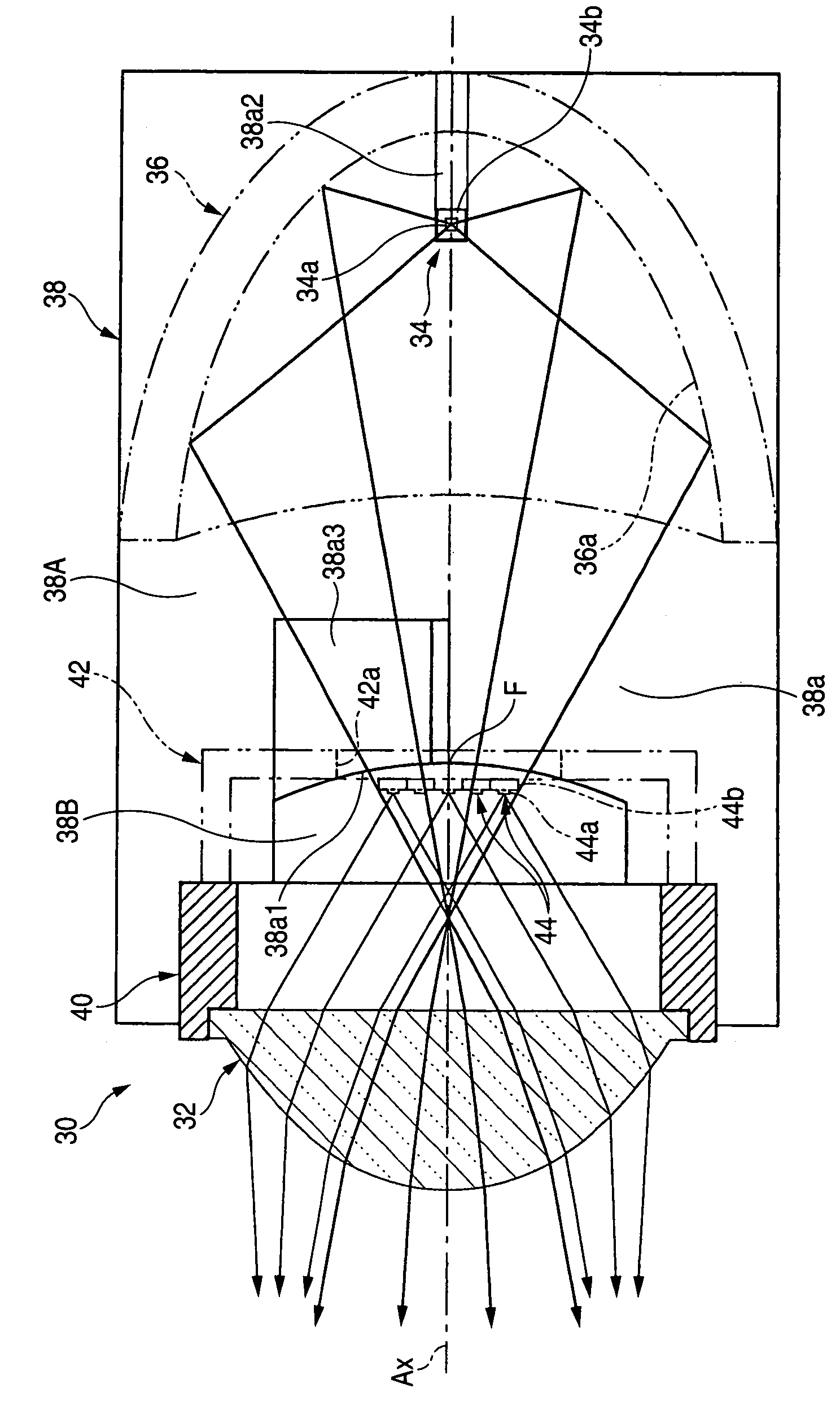
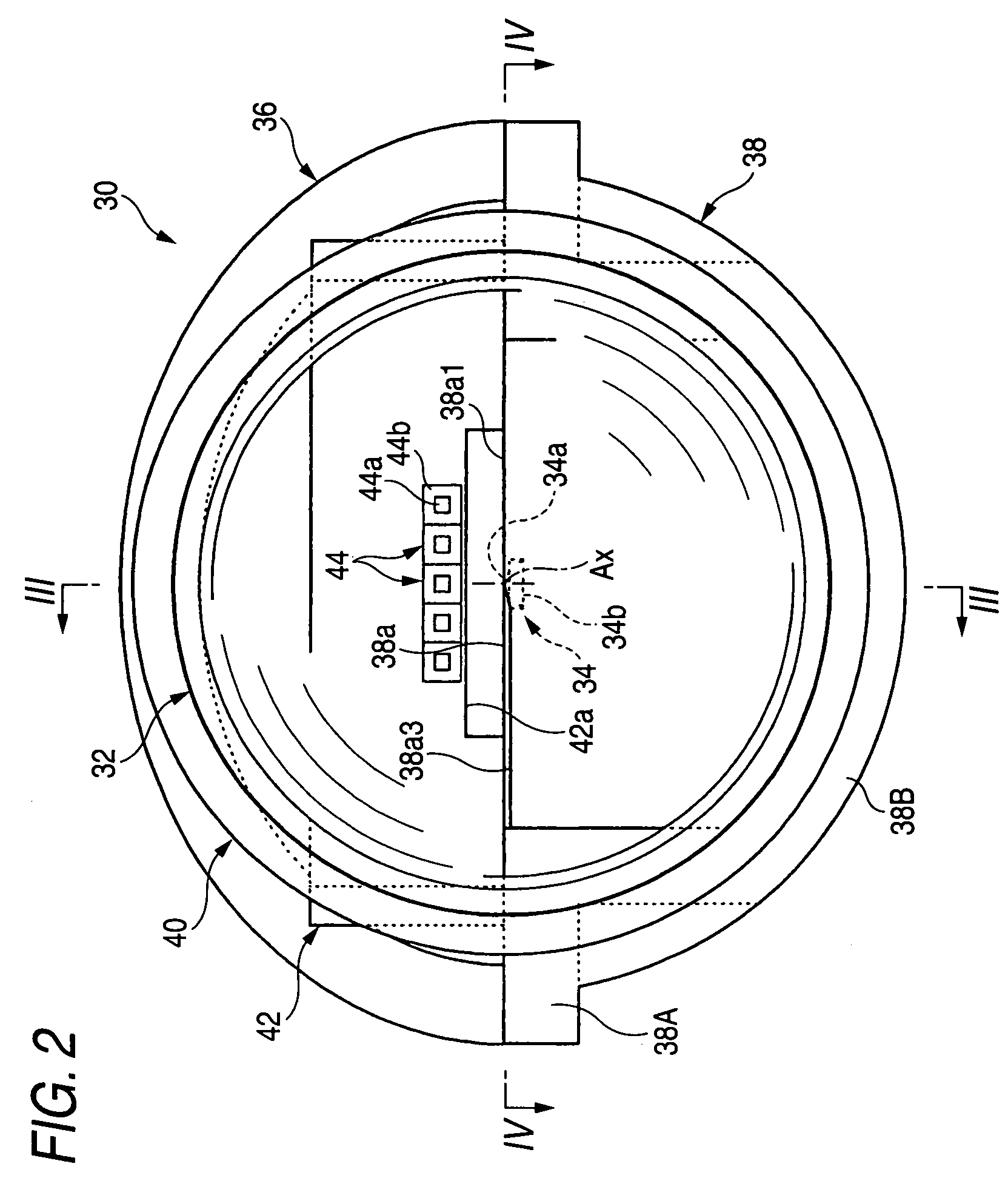
A lamp unit of a vehicle headlamp characterized in a lamp unit of a vehicle headlamp includes a projecting lens arranged on an optical axis extended in a front and rear direction of a vehicle, a first light emitting element arranged on a rear side of a rear side focal point of the projecting lens, and a reflector for reflecting light from the first light emitting element to a front side to be proximate to an optical axis. A vicinity of a rear side focal face of the projecting lens is arranged with a plurality of second light emitting elements for emitting light to the projecting lens.

Description

[0001]This application claims foreign priority from Japanese Patent Application No. 2006-048363, filed on Feb. 24, 2004, the entire contents of which are hereby incorporated by reference.BACKGROUND OF THE INVENTION[0002]1. Field of the Invention[0003]The present invention relates to a lamp unit of a vehicle headlamp, particularly relates to a lamp unit of a projector type constituting a light source by a light emitting element of a light emitting diode or the like.[0004]2. Related Art[0005]In recent years, there has been adopted a lamp unit constituting a light source by a light emitting element of a light emitting diode or the like also in a vehicle headlamp.[0006]For example, “Patent Reference 1” describes a lamp unit of a so-called projector type including a projecting lens arranged on an optical axis extended in a front and rear direction of a vehicle, a light emitting element arranged on a rear side of a rear side focal point of the projecting lens, and a reflector for reflecti...

Claims


Application Information

Patent Timeline
Patent Type & Authority Patents(United States)
IPC IPC(8): B60Q1/02F21V21/00
CPCF21S48/1159F21S48/1163F21S48/145F21S48/1747F21S48/1335F21Y2101/02F21Y2113/00F21Y2115/10F21S41/143F21S41/155F21S41/323F21S41/43F21S41/663F21S41/153F21S41/151F21S41/148
Inventor KOMATSU, MOTOHIRO
Owner KOITO MFG CO LTD
Learn More