Disk drive carrier assembly

a technology of carrier assembly and drive, which is applied in the direction of electric apparatus casing/cabinet/drawer, record information storage, instruments, etc., can solve the problems of long assembly time, vibration, and difficult to remove the mounting tray from the computer,

Inactive Publication Date: 2009-03-31
HONG FU JIN PRECISION IND (SHENZHEN) CO LTD +1
View PDF23 Cites 61 Cited by
  • Summary
  • Abstract
  • Description
  • Claims
  • Application Information

AI Technical Summary

Problems solved by technology

This method substantially requires a long assembling time, and will produce vibrations when the screws are installed or removed.
However, it is not easy to remove the mounting tray from the computer when the drive unit needs to be changed, and it is not easy to mount the tray to the computer.

Method used


Image

  • Disk drive carrier assembly
  • Disk drive carrier assembly
  • Disk drive carrier assembly

Examples


Embodiment Construction

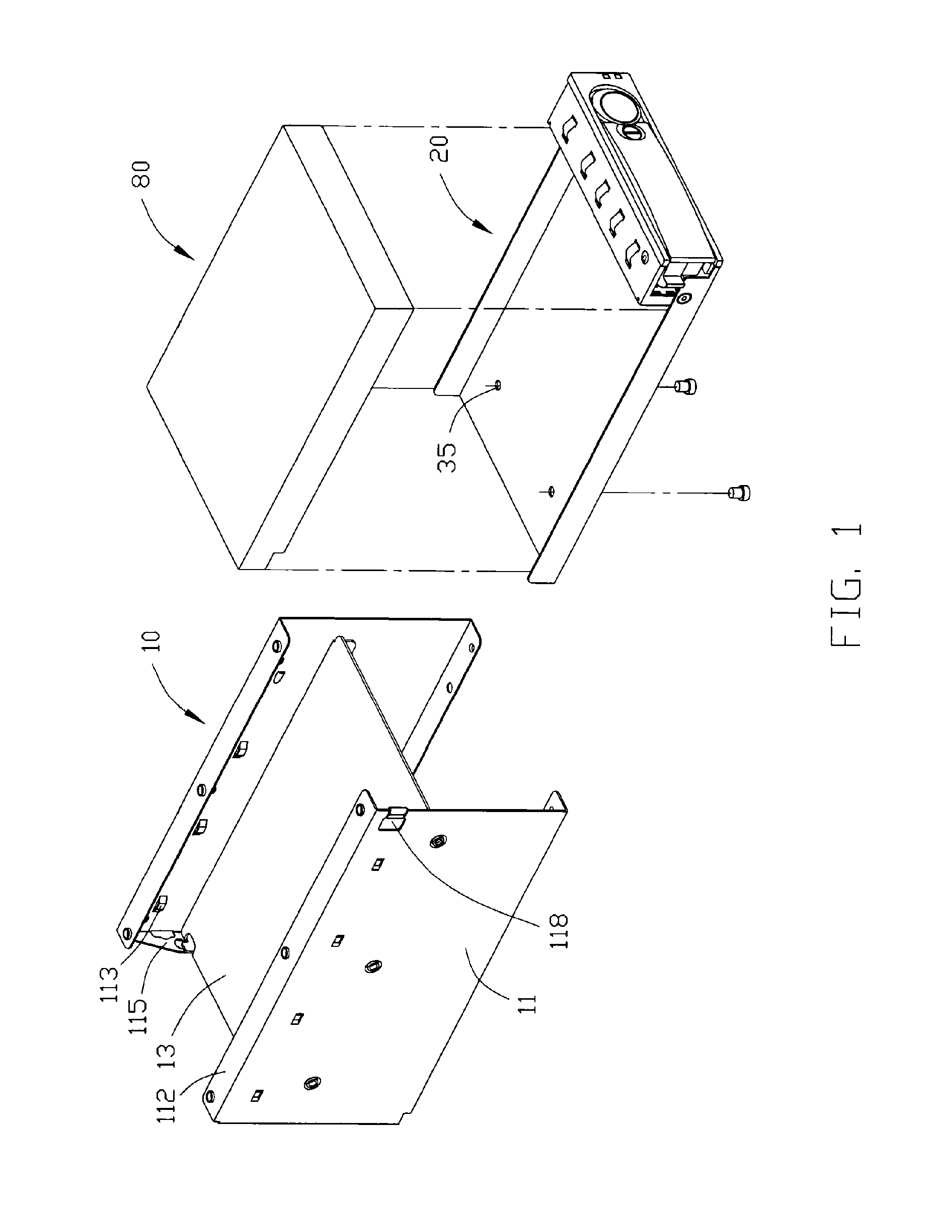
[0015]Referring to FIG. 1, a disk drive carrier assembly for mounting a disk drive 80 includes a bracket 10, and a disk drive carrier 20.

[0016]The bracket 10 includes a pair of parallel side plates 11, and an interlayer 13 being perpendicularly sandwiched therebetween. Each side plate 11 has a top flange 112 extending thereon. A plurality of guides 113 is formed in along a same horizontal line on each side plate 11 above the interlayer 13. A rear flange 115 extends along a back edge of the interlayer 13 from a back edge of each side plate 11. The two side plates 11, the top flanges 112, and the interlayer 13 form a slideway. A securing opening 118 is defined in a front side of one side plate 11 above the interlayer 13.

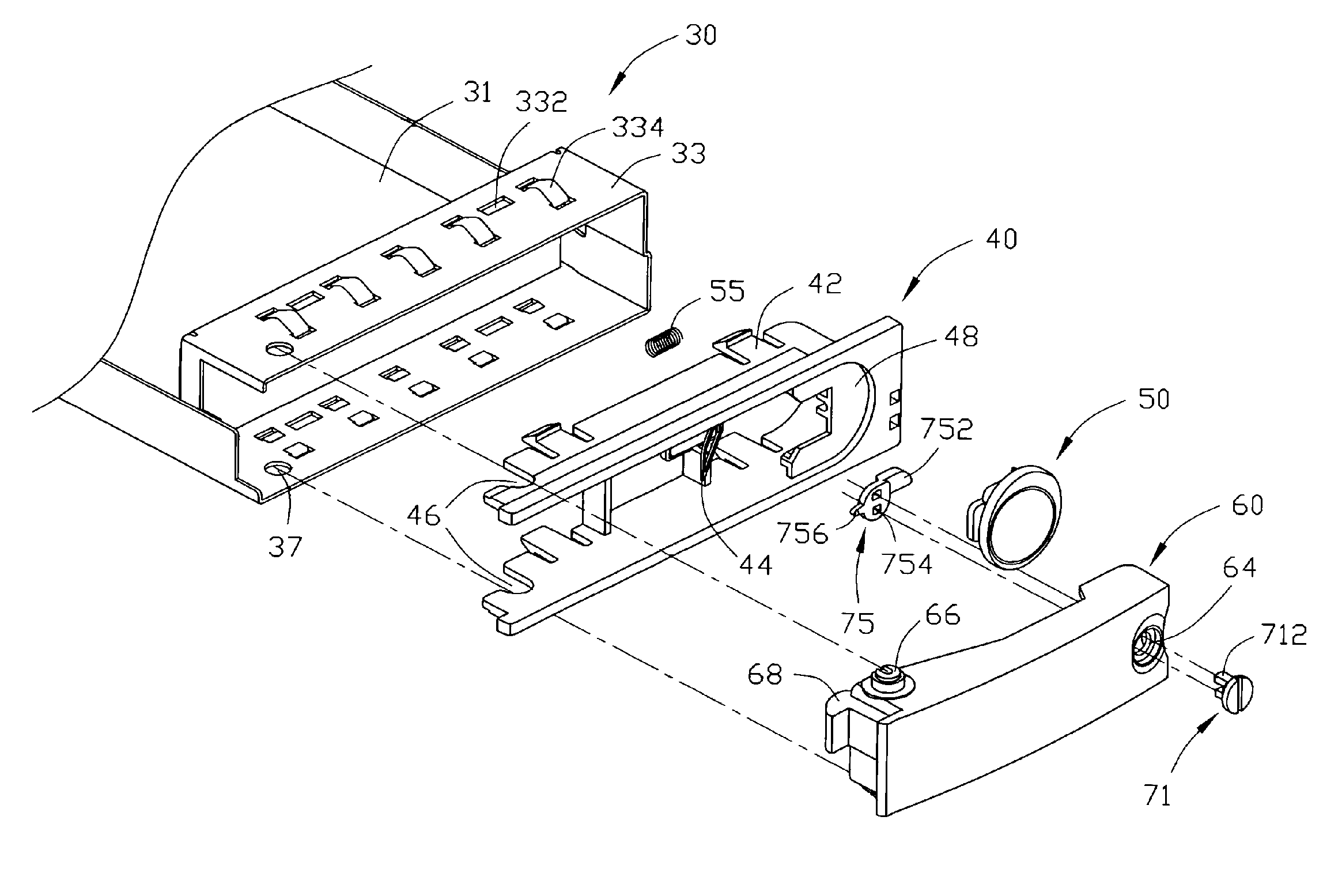
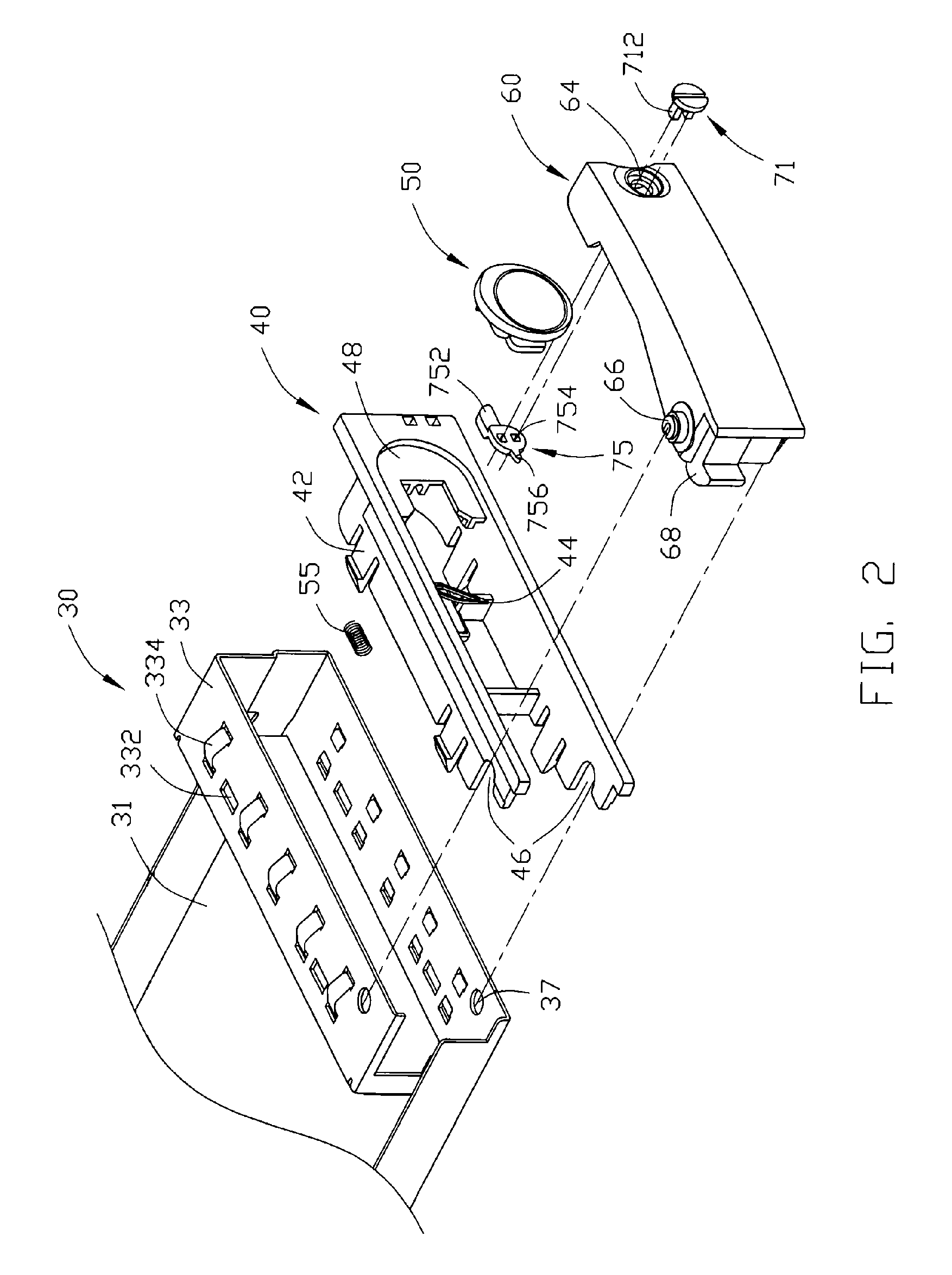
[0017]Referring also to FIG. 2, the disk drive carrier 20 includes a tray 30, a front panel 40, and a handle 60.

[0018]The tray 30 includes a disk drive holder 31, and a front receiver 33. The disk drive holder 31 has a pair of side walls. The holder 31 defines a pair o...


PUM


Abstract

A disk drive carrier assembly includes a disk drive (80), a bracket (10), and a carrier (20). The bracket includes a pair of parallel side plates (11) with a slideway defined therebetween for guiding the disk drive in a direction parallel to the side plates into the bracket. A securing opening (118) is defined in one of the side plates. The carrier includes a tray (30) for receiving the disk drive. A handle (60) is pivotably attached to the tray at an axis parallel to the side plates. A stop (68) is formed on an end of the handle for engaging with the securing opening of the bracket. A locking member (75) is rotatably attached to a free end of the handle from an inner side thereof.

Description

FIELD OF THE INVENTION[0001]The present invention relates to a carrier assembly, and more particularly to a disk drive carrier assembly which is used for holding a disk drive and mounting the disk drive to a bracket of a computer or related equipment.DESCRIPTION OF RELATED ART[0002]In a conventional method, a plurality of screws is used in installing / removing a disk to / from a computer or related equipment. This method substantially requires a long assembling time, and will produce vibrations when the screws are installed or removed. Subsequently a drive is mounted to a disk drive carrier. The drive carrier can help protect the drive from being damaged during installation.[0003]A mounting tray is provided to enable the mounting of a drive unit. The conventional mounting tray includes two stepped side members provided with studs for engaging side fixing holes in the drive units. The side members are joined by a flexible member that allows the side members to be flexed out of a normal ...

Claims


Application Information

Patent Timeline
Patent Type & Authority Patents(United States)
IPC IPC(8): G06F1/16H05K7/16
CPCG06F1/187G11B33/128
Inventor TAO, LANGCHEN, LI-PING
Owner HONG FU JIN PRECISION IND (SHENZHEN) CO LTD
Why Eureka
Try Eureka