Audiometer receiver and audiometer

a technology for audiometers and receivers, applied in the field of audiometer receivers and audiometers, can solve the problems of uneven characteristics of the receiver for an audiometer, requiring calibration, and unable to carry out audiometric tests while on site, so as to achieve the effect of merely calibrating the sound pressur

Active Publication Date: 2009-05-05
RION COMPANY
View PDF7 Cites 6 Cited by
  • Summary
  • Abstract
  • Description
  • Claims
  • Application Information

AI Technical Summary

Benefits of technology

[0009]It is therefore an object of the present invention to provide an improved audiometer receiver and an audiometer with the audiometer receiver which can solve the problems stated above and can output calibrated sound pressure merely by connecting the audiometer receiver to an audiometer body.

Problems solved by technology

A receiver for an audiometer has uneven characteristics and requires calibration when connected to an audiometer.
However, conducting calibration at a medical site becomes a burden to a hospital and a manufacturer because it is difficult to secure the time and place for the calibration.
Further, in the case where the audiometer is brought into the manufacturer's factory for the calibration, an audiometric test can not be carried out while the audiometer is taken away from the hospital.
Thus, the calibration at the manufacturer's factory also becomes a burden to the patient and the hospital.

Method used


Image

  • Audiometer receiver and audiometer
  • Audiometer receiver and audiometer
  • Audiometer receiver and audiometer

Examples


Embodiment Construction

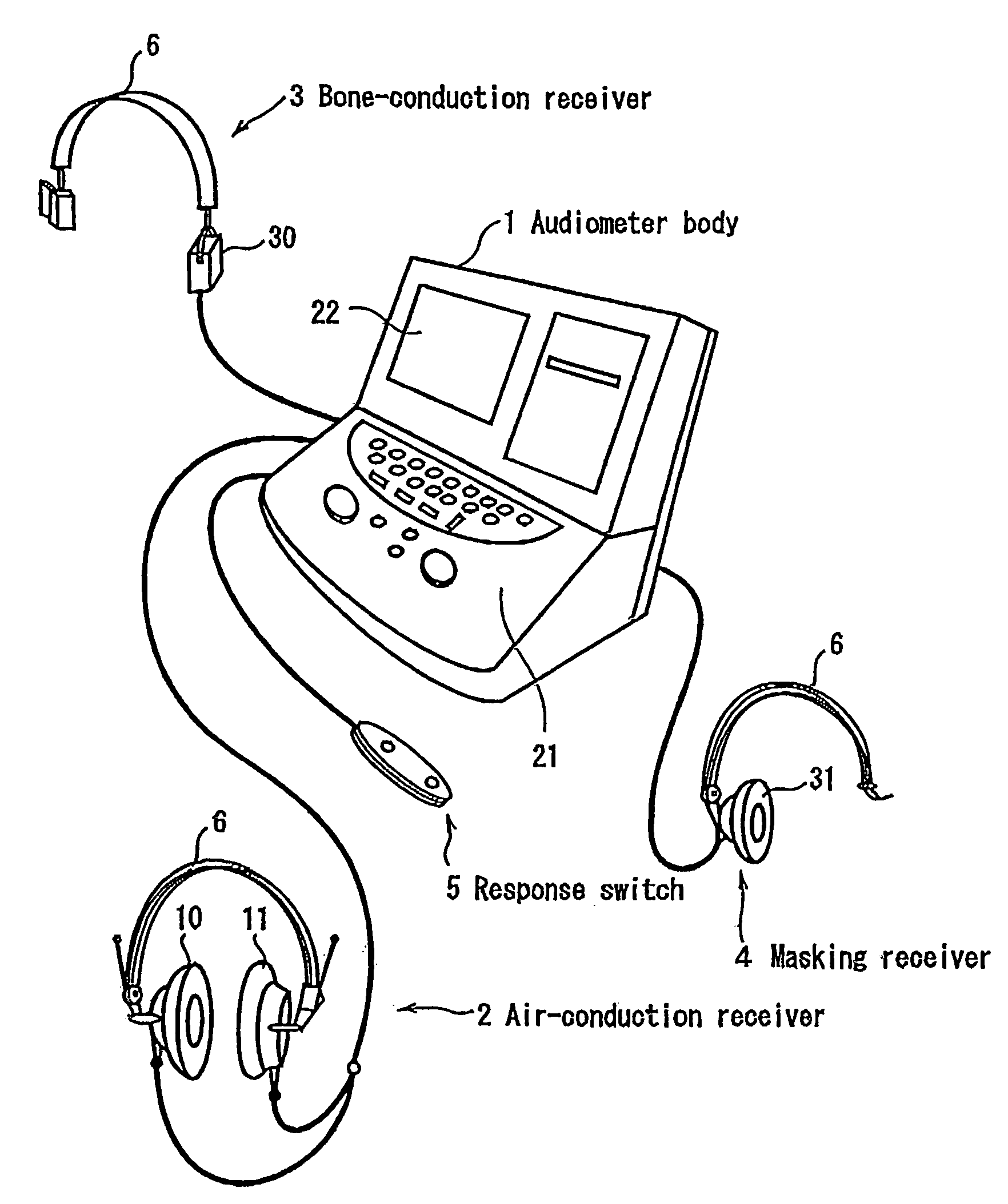
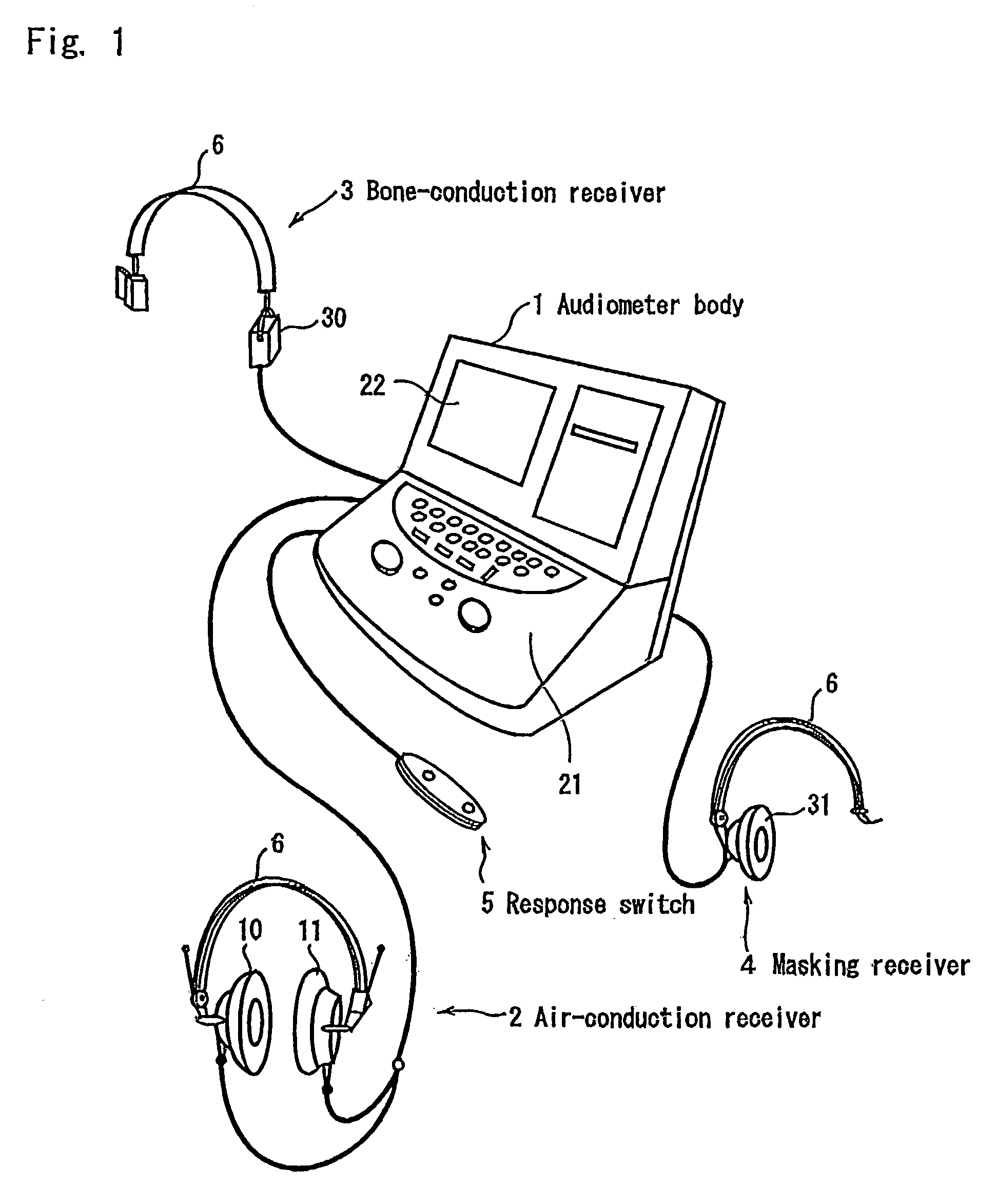
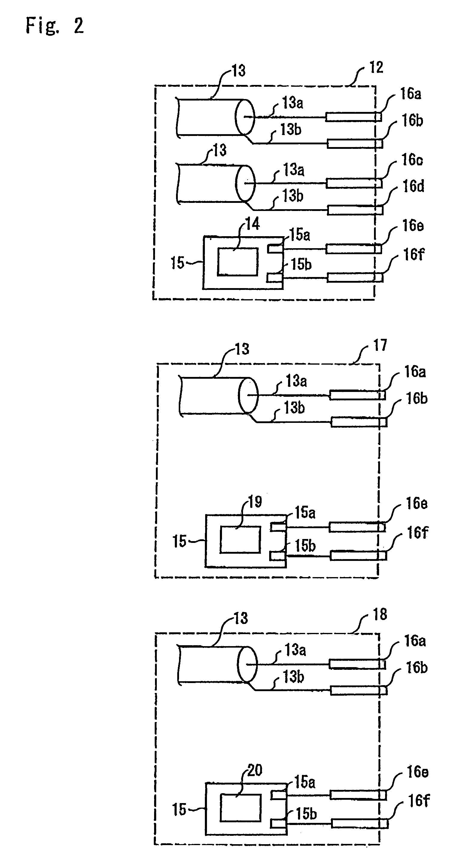
[0018]A preferred embodiment of the present invention will now be described with reference to the accompanying drawings. FIG. 1 is a schematic perspective view of an audiometer according to the present invention, FIG. 2 is a schematic diagram of a connector of an audiometer receiver according to the present invention, and FIG. 3 is a block diagram of the audiometer.

[0019]As shown in FIG. 1, an audiometer according to the present invention consists of an audiometer body 1, an air-conduction receiver 2, a bone-conduction receiver 3, a masking receiver 4, and a response switch S. Each receiver 2, 3 and 4 is connected to a headband 6 so that a test subject can wear it during an audiometric test.

[0020]The air conduction receiver 2 is composed, as shown in FIGS. 1 and 2, of a right receiver 10, a left receiver 11, a connector 12 for connecting to the audiometer body 1, and two coaxial cables 13 for connecting the right receiver 10 and the left receiver 11 to the connector 12, respectively...


PUM

PropertyMeasurementUnit
frequencyaaaaaaaaaa
pressureaaaaaaaaaa
timeaaaaaaaaaa

Abstract

An audiometer having an air-conduction receiver, a bone-conduction receiver, a masking receiver and an audiometer body is provided, in which the air-conduction receiver, the bone-conduction receiver, and the masking receiver are respectively provided with serial ROMs in which identification information and calibration information of each receiver are stored. The audiometer body comprises a misconnection detector for detecting misconnection of each receiver, a calibration period judging mechanism for judging a calibration transition period of each receiver, and a correction amount computer for computing a correction amount of sound pressure based on the information stored in the serial ROMs.

Description

CROSS-REFERENCE TO RELATED APPLICATIONS[0001]The present application claims priority from Japanese patent application 2006-132700, filed 11 May 2006. The entire disclosure of the referenced priority document is incorporated herein by reference.BACKGROUND OF THE INVENTION[0002]1. Field of the Invention[0003]The present invention relates to a receiver for an audiometer and an audiometer, which are used in an audiometric test.[0004]2. Description of the Prior Art[0005]A receiver for an audiometer has uneven characteristics and requires calibration when connected to an audiometer.[0006]In a conventional calibration method, it is known that the audiometer and its receiver are regarded as a pair of systems which are not interchangeable, their serial numbers are controlled in pairs, and their calibration information is stored in a memory which is provided in the audiometer. The audiometer outputs calibrated sound pressure from the receiver for the audiometer (hereinafter referred to as “au...

Claims


Application Information

Patent Timeline
Patent Type & Authority Patents(United States)
IPC IPC(8): G01N29/04G01N29/30H04R29/00
CPCA61B5/121
Inventor NOJIMA, YASUO
Owner RION COMPANY
Why Eureka
Try Eureka