
Microtitre plate with a relieved perimeter

a microtitre plate and perimeter technology, applied in the field of microtitre plates, can solve the problems of testing protocols that cannot access only a subset of wells on the microtitre plate, may arise problems, and cannot achieve the effect of achieving the effect of reducing the number of wells, and avoiding the use of microtitre plates

Active Publication Date: 2009-05-05
CAPLIPER LIFE SCI INC
View PDF7 Cites 94 Cited by
  • Summary
  • Abstract
  • Description
  • Claims
  • Application Information

AI Technical Summary

Benefits of technology

Enables efficient robotic handling of microtitre plates and tip trays interchangeably, allowing for flexible access to subsets of wells, maintaining standard compatibility and reducing the need for longer, less efficient handling strategies.

Problems solved by technology

However, these same commercial pressures also tend to constrain such improvements to be compatible with the installed base of the testing apparatus used by the industry.
One aspect of the testing process where these concerns intersect lies in the inability to access only a subset of the wells on the microtitre plate.
If for some reason only a subset of the wells on the microtitre plate are to be treated at some point, problems may arise.
Thus, testing protocols must either forego this strategy or employ longer, less efficient strategies to accomplish the same end.

Method used


Image

  • Microtitre plate with a relieved perimeter
  • Microtitre plate with a relieved perimeter

Examples


first embodiment

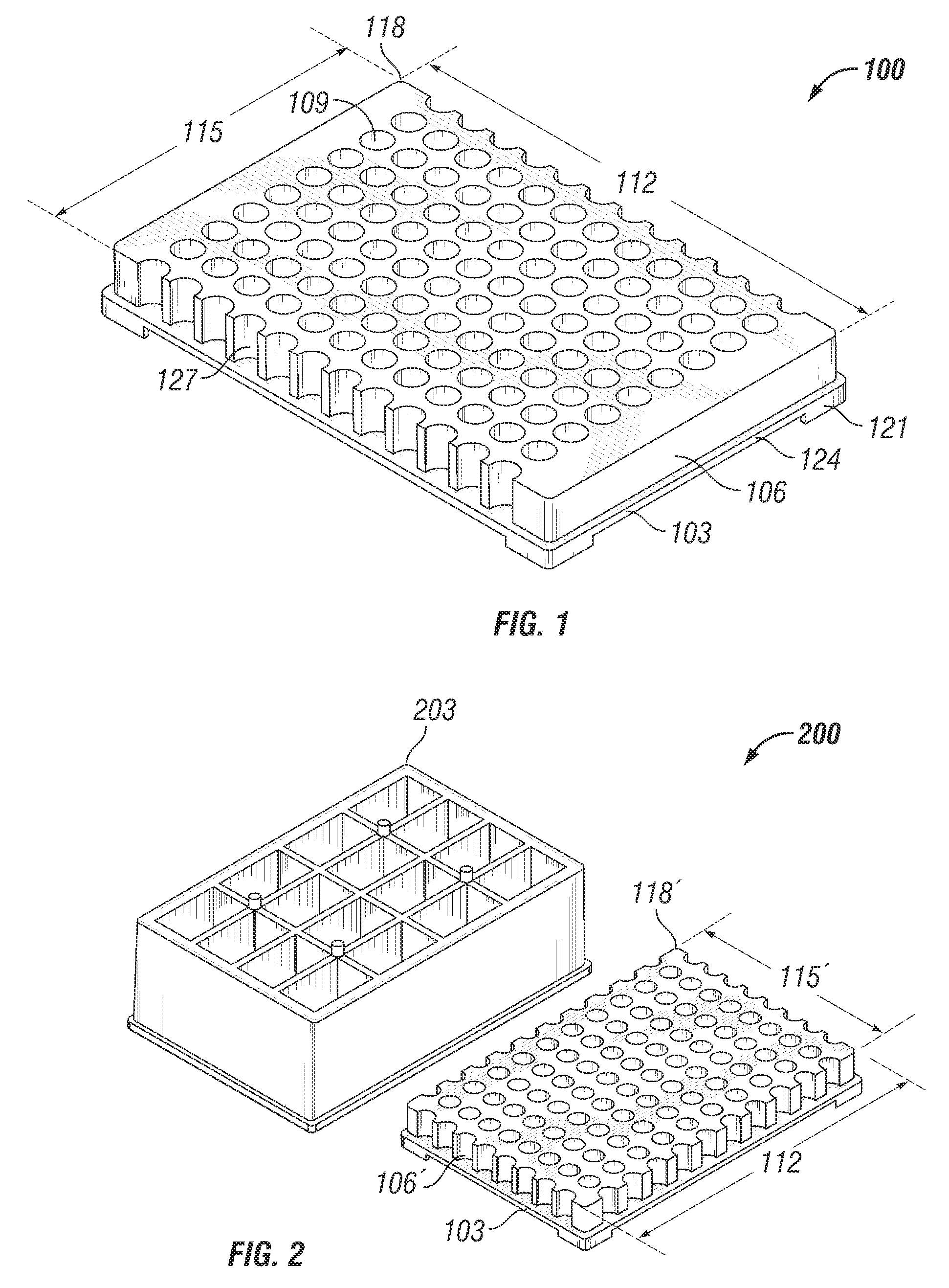
[0017]More particularly, FIG. 1 illustrates a microtitre plate 100 in a first embodiment in accordance with the present invention. The microtiter plate 100 comprises a base 103 and a holding section 106 extending from the base 103. The holding section 106 defines a plurality of wells 109 (only one indicated). The number of wells 109 is not material to the practice of the invention and will be implementation specific. In accordance with commonly accepted standards, the holding section 106 of the illustrated embodiment defines 96, 384, or 1,536 wells 109.

[0018]In this particular embodiment, the microtitre plate 100 has a rectangular geometry for both the base 103 and the holding section 106. Note that the base 103 and holding section 106 may have differing geometries in alternative embodiments. Because of the rectangular geometry, the microtitre plate 100 includes two long sides 112 and two short sides 115 (only one of each indicated) that define a perimeter 118 for the microtitre pla...

second embodiment

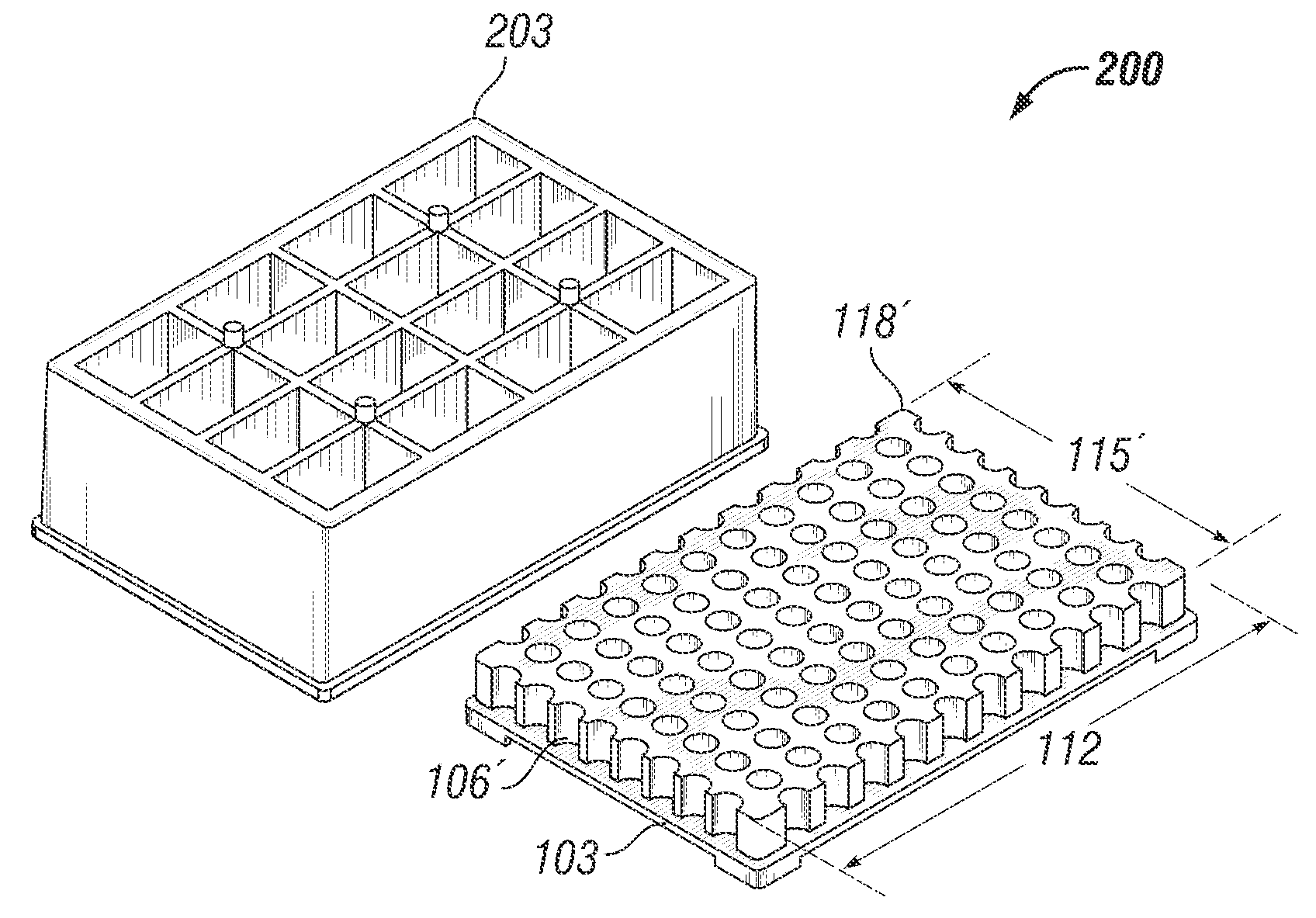
[0021]Turning now to FIG. 2, a microtitre plate 200 in accordance with the present invention is illustrated. FIG. 2 also shows an optional tip carrier 203 that may be snapped onto the microtitre plate 200 in some embodiments in accordance with conventional practice. The design of the microtitre plate 200 is similar to that of the microtitre plate 100, with like parts bearing like numbers. However, one difference is that the short sides 115′ are also horizontally relieved. The additional row / column intersection presented by this difference permits the robotic handling equipment to pick up a single fluid dispensing tip at the corner 206 of the microtitre plate 200, which provides single well pipetting in addition to row / column pipetting for serial dilutions. The perimeter 118′ of the microtitre plate 200 is designed with scalloped edges extending the pattern of locations that can accommodate an array of tips. This feature allows for the liquid handling head (not shown) to engage the t...


PUM


Abstract

A microtitre plate having a relieved perimeter includes a plate defining a plurality of wells and the perimeter of the plate is horizontally relieved. Alternatively, a microtitre plate may include a base and a holding section extending from the base. The holding section defines a plurality of wells and the perimeter thereof being horizontally relieved.

Description

BACKGROUND OF THE INVENTION[0001]The earlier effective filing date of co-pending U.S. Provisional Application Ser. No. 60 / 678,625, entitled “Microtitre Plate With a Relieved Perimeter,” filed May 6, 2005, in the name of the inventors Richard P. Bunch, et al. is hereby claimed and the application is hereby incorporated by reference for all purposes as if expressly set forth herein verbatim.[0002]1. Field of the Invention[0003]The present invention pertains to microtitre plates.[0004]2. Description of the Related Art[0005]Many types of testing dispose samples in the wells of a microtitre plate. Sometimes the samples are disposed directly into the wells. Other times, sample holders are used to transfer samples into or out of the wells of the microtitre plates. In commercial applications, the volume of testing is important both for economies of scale and for quick turnaround. Accordingly, robotic equipment has been developed to automate the testing, which includes the handling of microt...

Claims


Application Information

Patent Timeline
Patent Type & Authority Patents(United States)
IPC IPC(8): B01L3/00
CPCB01L3/5085B01L2200/025B01L2300/0829
Inventor BUNCH, RICHARD P.SIMMONS, FREDERICK D.ALDERMAN, EDWARD M.
Owner CAPLIPER LIFE SCI INC
Learn More