Row unit down pressure assembly

a technology of assembly and row unit, applied in the field of row unit down pressure assembly, can solve the problems of lack of discrete adjustment visual indicators, and the lack of adjustmen

Active Publication Date: 2009-06-02
BLUE LEAF I P INC
View PDF20 Cites 76 Cited by
  • Summary
  • Abstract
  • Description
  • Claims
  • Application Information

AI Technical Summary

Problems solved by technology

This adjustment also lacks a visual indicator of discrete adjustments.

Method used


Image

  • Row unit down pressure assembly
  • Row unit down pressure assembly
  • Row unit down pressure assembly

Examples


Embodiment Construction

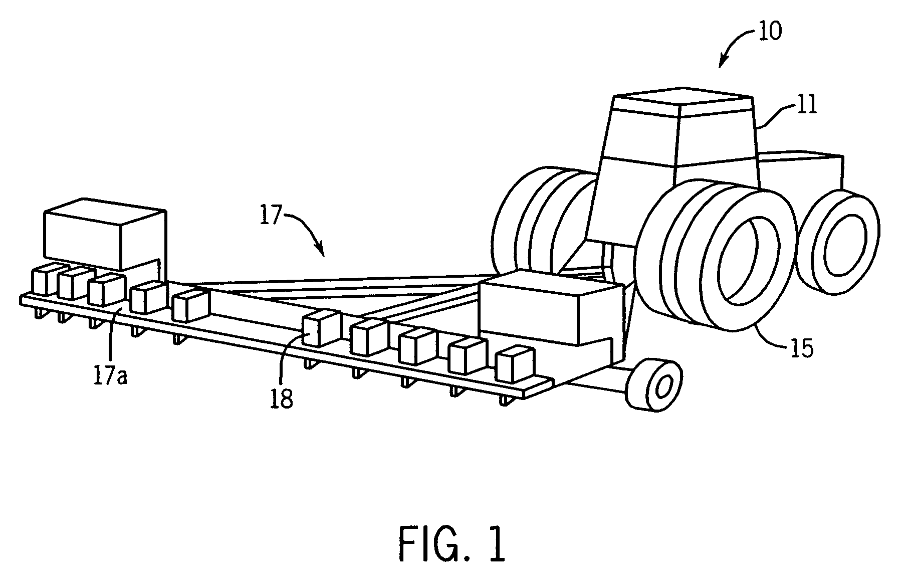
[0025]Referring to FIG. 1, a tractor 10 is seen pulling an agricultural implement 17, which in this case, is a seed planter. The present invention is also be applicable to cultivators, tillers and other types of agricultural implements. The tractor 10 has a cab 11 and large rear drive wheels 15. The agricultural implement 17 has a trailing planter sub-bar 17a across which individual seed hoppers or row units 18 are spaced apart to dispense seeds along rows made in the ground by other parts of the planter.

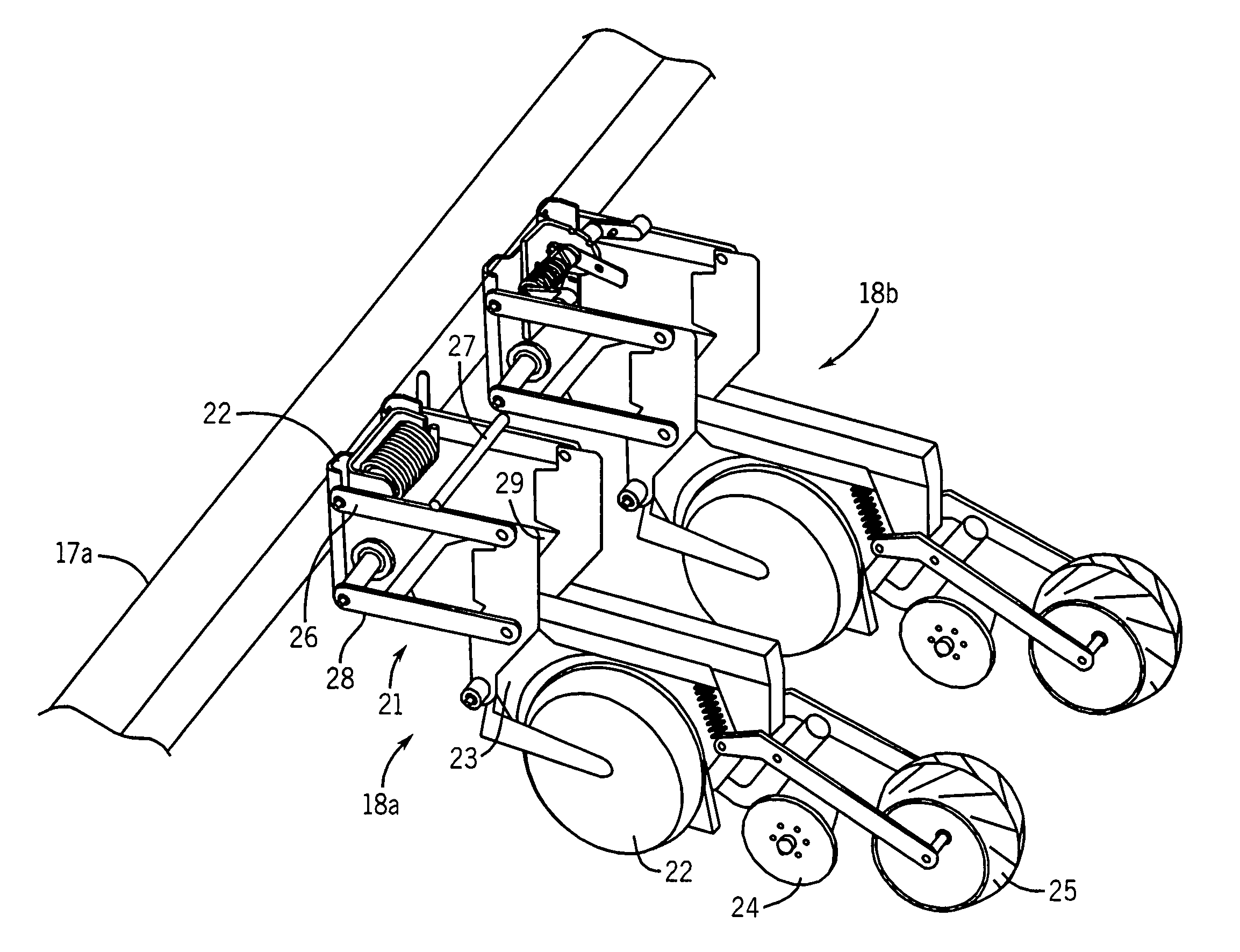
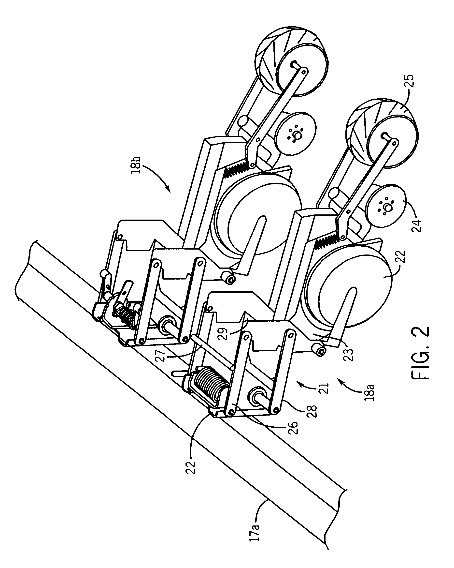
[0026]FIG. 2 shows a detail perspective view of the rear end of the implement 17 and a trailing planter sub-bar 17a. Two row units 18a, 18b are each attached to the bar 17a though attachment frame 21. The row units 18a, 18b each have a pair of depth gauge wheels 22, a retractable tool 23 carried between the depth gauge wheels 22, a pair of furrow closing wheels 24 and a trailing compression wheel 25 which are conventional components known in row units in the art. Each attachment fra...


PUM


Abstract

A down pressure assembly for incorporation into an agricultural implement to be pulled by a tractor (10) has an attachment frame (21) for attachment between a portion of the agricultural implement and at least two wheels (22) of a row unit (18) for traveling along the ground, the row unit (18) also having a tool (23) disposed between the two wheels (22) for engaging the ground, the down pressure assembly also having at least one torsion element (41, 50) disposed on the frame (21), with the torsion element (41, 50) having one fixed mounting to the frame (21) and one adjustable mounting to the frame (21), and the assembly further having an adjustment mechanism (37, 60) for varying the torsion of the torsion element (41, 50) at the adjustable mounting; and at least one down pressure member (36, 56, 57) for receiving a force from the torsion element to apply a downward force to the top members (26, 27) of the frame (21).

Description

CROSS-REFERENCE TO RELATED APPLICATIONS[0001]Not applicable.STATEMENT REGARDING FEDERALLY SPONSORED RESEARCH OR DEVELOPMENT[0002]Not applicable.DESCRIPTION OF THE BACKGROUND ART[0003]This invention relates to farm implements that are pulled behind a tractor for tilling, planting or cultivating.[0004]Farm implements include seed planters, cultivators, tillers and other implements. Typically, these implements have a number of individual row units spaced along a trailing bar on the implement, each row unit operating in a row or furrow being planted or cultivated.[0005]It is desired to provide down pressure in such units to keep them from bouncing or leaving a furrow. One method of creating down pressure uses tension springs to create a load between two links. As the links move in parallel, the spring begins to stretch. The loading of the spring tends to pull on the links to apply pressure to keep a working tool on the row unit in the ground.[0006]Compression springs can also be used to...

Claims


Application Information

Patent Timeline
Patent Type & Authority Patents(United States)
IPC IPC(8): A01B15/00
CPCA01B63/26A01C7/205
Inventor BETTIN, LEONARD A.HARNETIAUX, TRAVIS LESTER
Owner BLUE LEAF I P INC
Why Eureka
Try Eureka