Offset stem tibial implant

a tibial implant and stem technology, applied in the field of tibial implants with stems, can solve the problems of cost, logistics and efficiency, and the inability to adjust the relative positioning of the two tibial axes, and achieve the effect of facilitating the movement of the surgeon

Inactive Publication Date: 2009-06-09
CORIN
View PDF102 Cites 74 Cited by
  • Summary
  • Abstract
  • Description
  • Claims
  • Application Information

AI Technical Summary

Benefits of technology

[0019]Certain embodiments are also directed to a modular offset stem tibial implant which is easier to implant in the tibia and which behaves in a more satisfactory manner from an anatomical perspective, as well as providing a great adjusting freedom for its assembling.
[0022]With certain embodiments of the tibial implant, the adapter element, which allows the effective offset between the two tibial axes of the implant, is assembled as closely as possible to the tray, i.e. in the immediate vicinity of the distal surface of the plate of this tray. In other words, in contrast with tibial implants of the prior art, no pin is placed between this plate and the adapter element. Besides, thanks to the angular indexing features of the adapter element, the surgeon is able to adjust, for a given offset value between the first and the second tibial axes, value that is characteristic of the adapter element that is being used, the positioning of the second tibial axis all about the first tibial axis. Thus, without changing the adapter element, the surgeon freely adjusts, in a discrete manner, the relative positioning between the first and second tibial axes in all the horizontal plane, that is to say along both medio-lateral and antero-posterior directions.
[0031]It will be noted that this arrangement may be considered independently from the specific type of the assembling between the tray and the proximal part of the adapter element. In particular, this arrangement is really interesting for its compactness and its reliability, even if the adapter element is not assembled in the immediate vicinity of the distal surface of the plate of the tray.
[0032]In combination with this compact embodiment, the tibial implant according to certain embodiments comprises a locking element for locking the tray, the stem and the adapter element assembled to one another, which locking element is suitable for being at least partially introduced into the proximal aperture to be coupled to the distal end of the stem. In this manner, solely by manipulating this locking element, the surgeon carries out relative immobilization of the components of the tibial implant which are assembled to one another, this locking element therefore advantageously occupying a space left free in the proximal aperture of the adapter element.
[0033]To facilitate the movements of the surgeon, by allowing the surgeon to manipulate the locking element from the proximal side of the tray, the plate of the tray includes a through-aperture, which extends along the first tibial axis and into which the locking element is suitable for being introduced to extend as far as the proximal aperture when the plate and the adapter element are assembled to one another.

Problems solved by technology

These two solutions have the drawback of placing the effective area of the offset of the two axes at a significant depth of the tibial medullary canal.
In use, however, the left / right reversibility of the assembling between the tray and the adapter element is provided due to the fact that the respective cross sections of the protrusion and of the aperture are oblong, which enables no freedom for adjusting the relative positioning of the two tibial axes, except the freedom for choosing between the two opposed left / right configurations.
Consequently, a lot of adapter elements with different respective configurations for the angular offset between their proximal and distal parts are necessarily provided for the surgeon, which results in problems of costs, logistics and efficiency.

Method used


Image

  • Offset stem tibial implant
  • Offset stem tibial implant
  • Offset stem tibial implant

Examples


Embodiment Construction

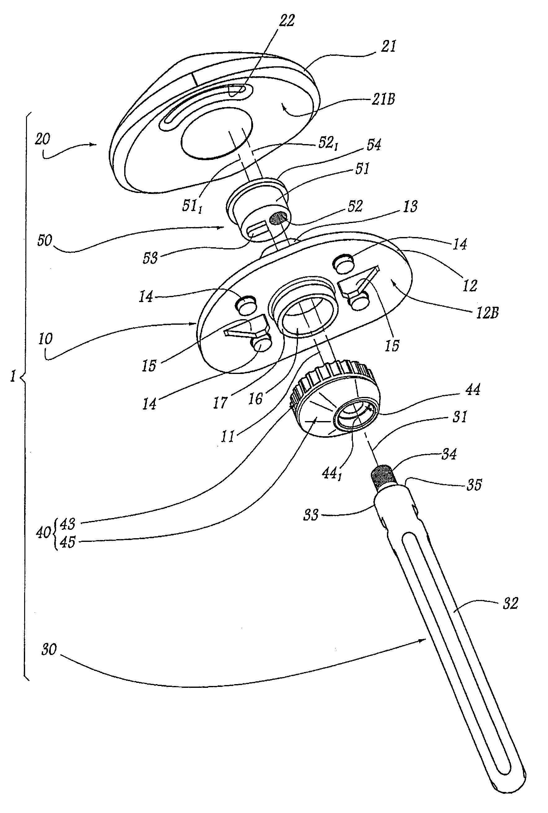
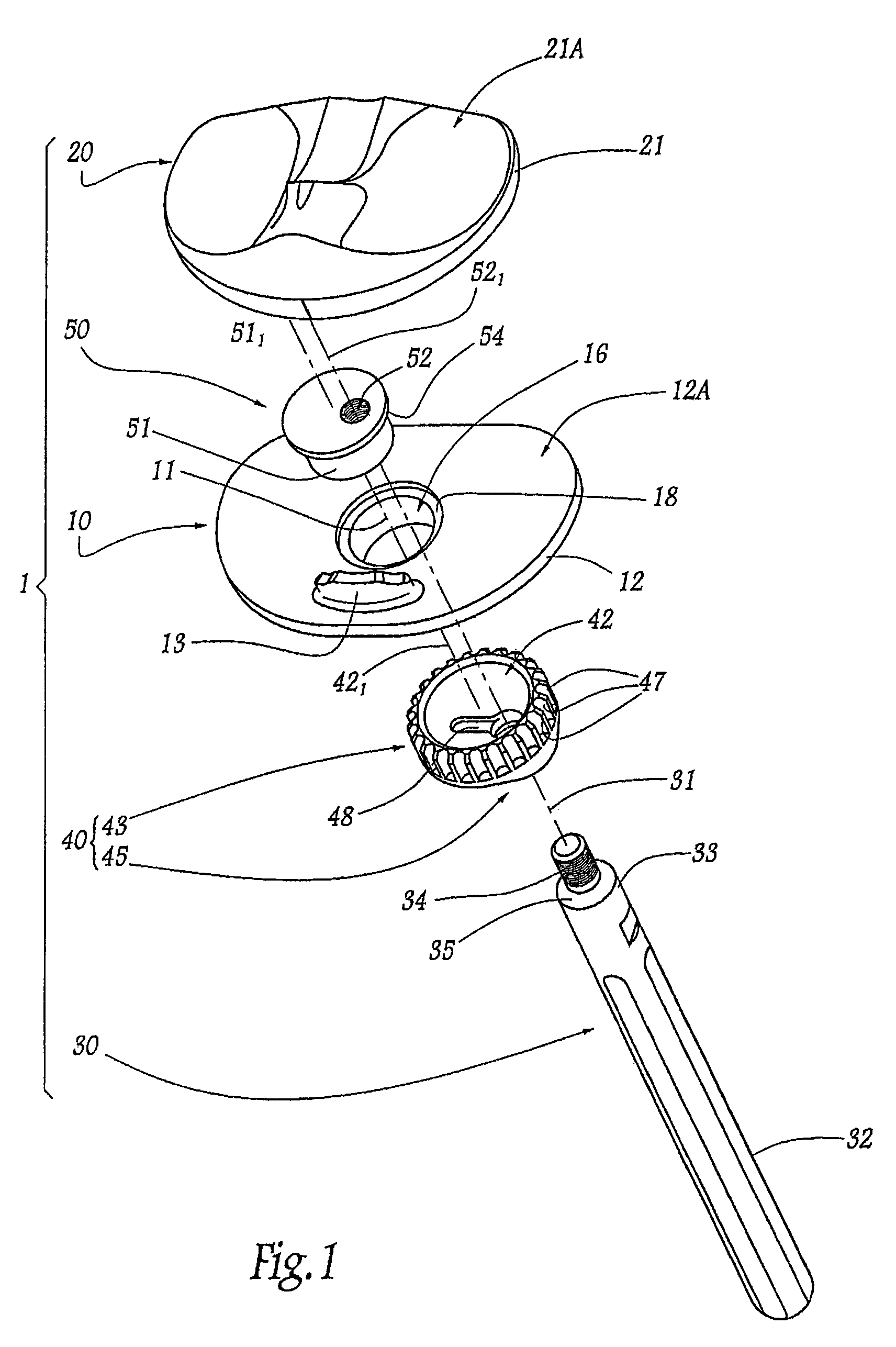
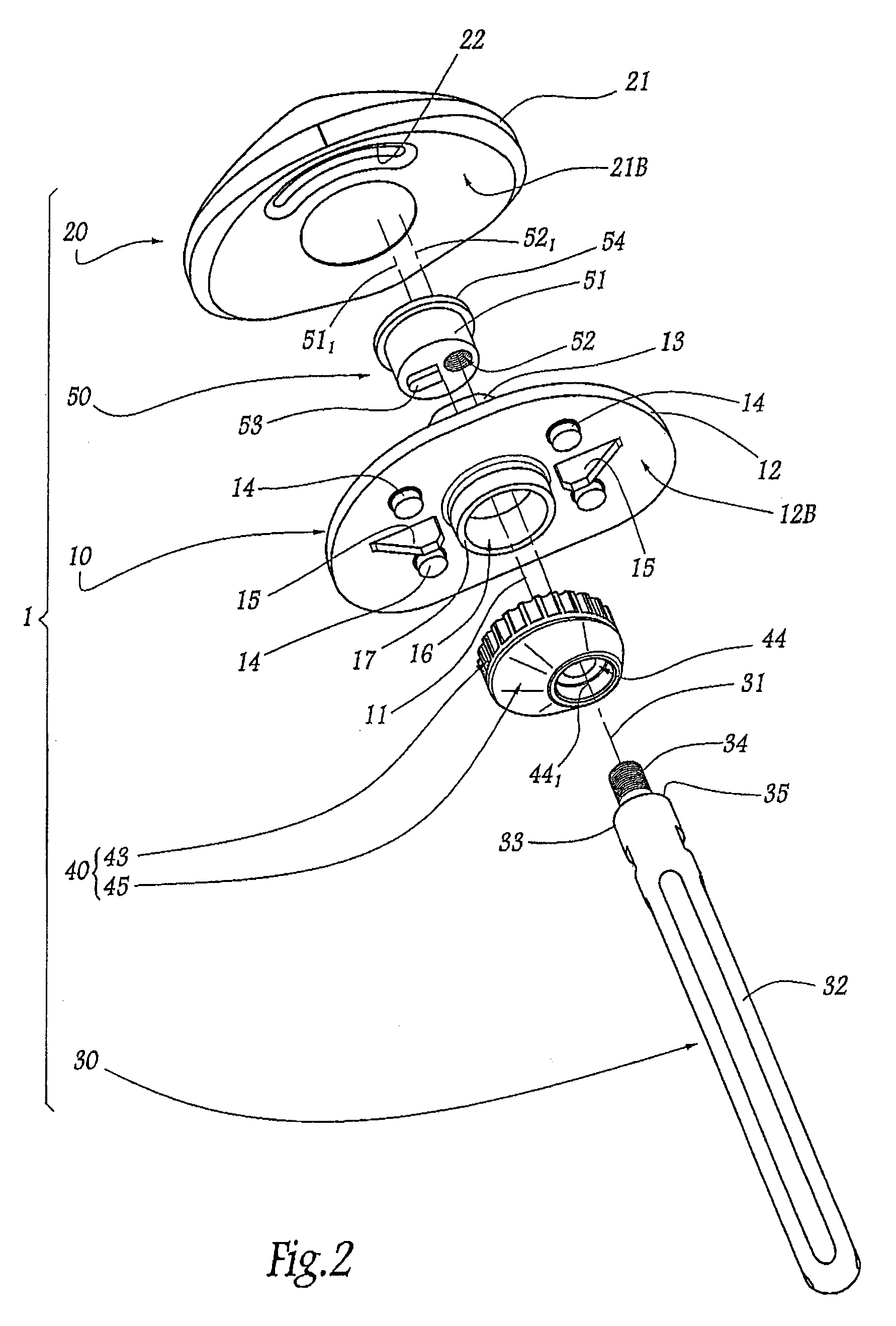
[0039]In FIGS. 1 to 3, a tibial implant 1 is shown forming part of a knee prosthesis of a human being. For convenience, the remainder of the description is oriented relative to the knee of a patient who is standing, such that the term “proximal” denotes a direction directed towards the knee joint while the term “distal” denotes a direction in the opposing direction. Similarly, the terms “upper” and “top” and in contrast, “lower” and “bottom” are understood to be relative to a largely vertical direction in relation to the ground on which the patient is standing, with the tibia thus extending in a substantially vertical manner.

[0040]The illustrated embodiment of implant 1 includes five separate components, able to be assembled to one another so that the implant has an assembled configuration allowing its implantation in one piece in the region of the tibia. The illustrated components include a tray 10, a pad 20, a stem 30, an adapter element 40 and a locking element 50, each of which ...


PUM


Abstract

A low-profile offset stem tibial implant includes a tray with a plate that extends transversely around a first tibial axis. The plate includes a distal surface adapted to engage against the prepared surface of the tibia. An engagement portion extends away from the distal surface of the plate substantially along the first tibial axis. A stem is provided with a distal end adapted to be introduced into the medullary canal of the tibia along a second tibial axis and a proximal end. One or more adapter elements are provided with a proximal portion sized to engage with the engagement portion of the plate along the first tibial axis. The adapter element also includes a distal portion adapted to engage with the proximal end of the stem along the second tibial axis. The adapter element permits adjustment of the medio-lateral and antero-posterior position of the second tibial axis relative to the first tibial axis. A plurality of indexing features are located at an interface between the plate and the adapter element to secure the tray in at least three discrete locations around the first tibial axis when in an assembled configuration.

Description

CROSS-REFERENCE TO RELATED APPLICATIONS[0001]The present application claims priority to prior French Application No. 0600913, filed Feb. 1, 2006, the entire specification of which is hereby incorporated by reference.FIELD OF THE INVENTION[0002]The present invention relates to an offset stem tibial implant that includes a stem adapted to be introduced into the medullary canal of the tibia and a tray adapted to be fixed to the upper end of the tibia. One or more adapter elements are used to offset the tray relative to a longitudinal axis of the stem. The low profile of the present offset stem tibial implant provides a number of advantages over the prior art.BACKGROUND OF THE INVENTION[0003]Tibial implants generally form part of a knee prosthesis and are typically associated with a femoral implant fixed to the lower end of the femur. A pad is on the tray of the tibial implant and articulated against the femoral implant. The pad can either be fixed or mobile relative to the tray.[0004]T...

Claims


Application Information

Patent Timeline
Patent Type & Authority Patents(United States)
IPC IPC(8): A61F2/36
CPCA61F2/389A61F2/30724A61F2/3868A61F2002/30136A61F2002/30329A61F2002/30354A61F2002/30594A61F2002/30604A61F2002/30878A61F2220/0025A61F2220/0033A61F2230/0004
Inventor ROCHETIN, OLIVIER
Owner CORIN
Why Eureka
Try Eureka