
Aircraft propulsion system

a propulsion system and aircraft technology, applied in the field of aircraft propulsion systems, can solve the problems of negative impact on flight performance, unsatisfactory engine operation efficiency, and difficulty in realizing the optimal engine disposition and engine sectional area for all flight conditions, and achieve the effect of high compatibility with the environmen

Inactive Publication Date: 2009-07-07
JAPAN AEROSPACE EXPLORATION AGENCY +1
View PDF17 Cites 90 Cited by
  • Summary
  • Abstract
  • Description
  • Claims
  • Application Information

AI Technical Summary

Benefits of technology

[0009]The present invention is contrived in view of the above problems of the conventional technologies, and an object of the present invention is to provide an aircraft propulsion system which can secure the optimum thrust and thrust vector for flight conditions, as well as the optimum sectional area for the engine, and which is highly compatible with the environment.

Problems solved by technology

High bypass-ratio turbofan engines, which are used for many highly efficient civil aircraft engines, have large air inlet sectional area (engine sectional area), and do not require thrust during high-speed cruise as much as during take-off, thus the excessively large sectional area of the engine increases the resistance of the aircraft, resulting in a negative impact on the flight performances.
For the purpose of simply increasing the thrust, an afterburner may be mounted in a rear portion of the engine to reduce the outer diameter of the fan, but actuation of the afterburner causes tremendous noise, and thus is not desirable in terms of the engine operation efficiency.
As described above, with normal fixed engines, it is difficult to realize the optimum engine disposition and engine sectional area for all the flight conditions.
Among the systems, mechanisms of moving engines, or thrust vectoring nozzles for deflecting nozzles are beneficial for military-aircraft use where prompt change in thrust vector in aircraft traffic, but are not so beneficial for the use of civil aircraft the majority of which have large bodies.
However, these are not so economical in terms of their limited effects, and their mechanisms tend to be complex.
The fact is that the mechanism of generating reverse thrust has somewhat complex mechanisms.
Further, the recent environmental compatibility, that is less noise and lower amount of emission gas, is one of the most important issues regarding the performances of aircraft engines.
However, there is a limit to the development of aircraft engines which are improved year by year in terms of environmental compatibility, thus new ideas for engine systems are necessary in order to improve the basic performances.
The problem in Japanese Patent Application Laid-Open No. 2003-137192 is that the turbofan engine with thrust vectoring mechanism is complex in terms of its mechanism, and the weight thereof is heavy.
H11-137192 has limited output, although it is compatible with the environment, thus the applicability to larger aircrafts is limited.

Method used


Image

  • Aircraft propulsion system
  • Aircraft propulsion system
  • Aircraft propulsion system

Examples


embodiment 1

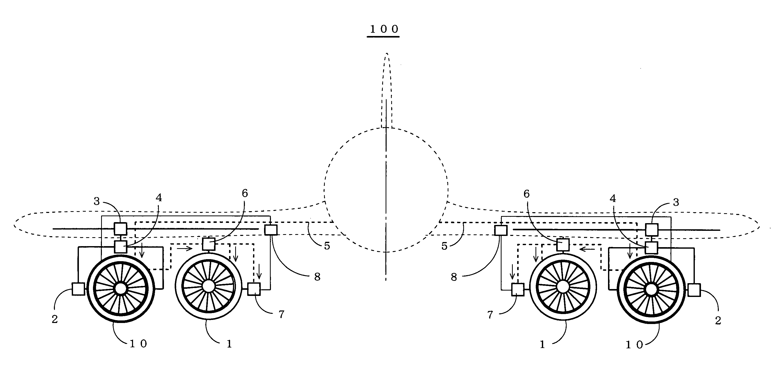
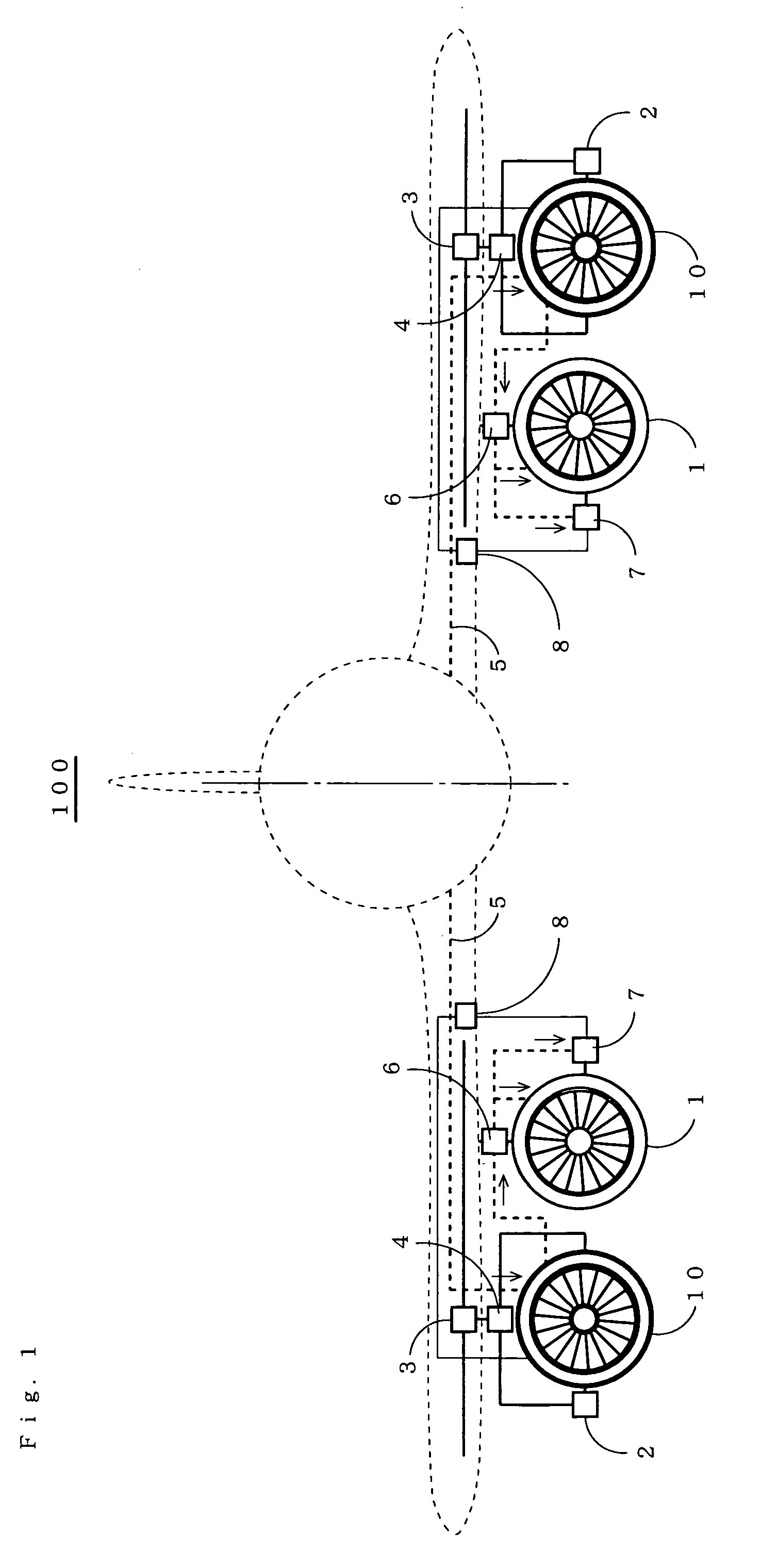
[0043]FIG. 1 is an explanatory diagram of a configuration, showing an aircraft propulsion system 100 of an embodiment of the present invention.

[0044]The aircraft propulsion system 100 comprises a turbo fan engine 1, 1 as a first propulsion unit for generating thrust, an electromagnetic driving fan 10, 10 as a second propulsion unit, a rotating mechanism portion 2, 2 as thrust vectoring means for vectoring a thrust vector of the electromagnetic driving fan, a slide mechanism portion 3, 3 as wing moving means for moving the electromagnetic driving fan with respect to a width direction of the wing and a wing chord direction, a storage mechanism portion 4, 4 as storage means for storing the electromagnetic driving fan in a wing or an external surface of the wing, a liquid fuel line 5, 5 which supplies liquid hydrogen which is provided as fuel in the turbofan engine while cooling each coil of the electromagnetic driving fan, a heat exchanger 6, 6 in which exhaust from the turbofan engine...


PUM


Abstract

To provide an aircraft propulsion system which can secure the optimum thrust and thrust vector for flight conditions, as well as the optimum sectional area for the engine, and which is highly compatible with the environment.An electrical generator is coupled to a turbofan engine, the electrical generator is driven by output power of the turbofan engine to output electric power, and an electromagnetic driving fan is driven by the electric power. On the other hand, after bringing each of coils in the electromagnetic driving fan to a superconductive state, liquid hydrogen is introduced to a heat exchanger, collects the energy of exhaust as heat, is then vaporized, and thereafter supplied to a combustor and to a fuel cell. Further, the electromagnetic driving fan is changed in its rotational phase by a rotating mechanism portion, is made movable in a width direction of a wing and a wing chord direction by a slide mechanism portion, and can be stored inside or outside the wing by a storage mechanism portion.

Description

BACKGROUND OF THE INVENTION[0001]1. Field of the Invention[0002]The present invention relates to an aircraft propulsion system, and particularly to an aircraft propulsion system which can secure the optimum thrust and thrust vector for flight conditions, as well as the optimum sectional area for the engine, and which is highly compatible with the environment.[0003]2. Description of the Related Art[0004]The optimum thrust, thrust vector, and sectional area for the engine are required in various flight conditions of an aircraft engine, such as take-off, cruise and landing conditions. For example, maximum thrust is required in a take-off condition, or thrust for increasing a direction of braking is required in a landing condition, whereas in a cruise condition are not required low air resistance. High bypass-ratio turbofan engines, which are used for many highly efficient civil aircraft engines, have large air inlet sectional area (engine sectional area), and do not require thrust duri...

Claims


Application Information

Patent Timeline
Patent Type & Authority Patents(United States)
IPC IPC(8): F02K1/00
CPCB64D27/24F01D15/10F02K3/06H02K7/1823Y02T50/671H02K55/00Y02T50/44Y02T50/62Y02T50/40Y02T50/60
Inventor OKAI, KEIICHITAGASHIRA, TAKESHIYANAGI, RYOJINOMURA, HIROSHI
Owner JAPAN AEROSPACE EXPLORATION AGENCY
Learn More