Single bolt deadend anchor clamp

a single bolt and anchor technology, applied in the direction of scaffold accessories, furniture parts, machine supports, etc., can solve the problems of affecting the clamping effect, the difficulty of balancing on an aerial platform, and the dependence of the clamping

Active Publication Date: 2009-07-21
HUBBELL INC
View PDF16 Cites 16 Cited by
  • Summary
  • Abstract
  • Description
  • Claims
  • Application Information

AI Technical Summary

Benefits of technology

[0015]By forming the anchor clamp in this manner, end users can counterbalance a load between the keeper and the retaining groove. The bolt and keeper are biased toward an anchor / relief end so when the bolt is tightened, the keeper comes into contact with the cable in this biased location.

Problems solved by technology

One drawback of conventional deadend anchor clamps is that a lineman must remove a plurality of nuts and washers.
As this operation is typically completed on energized lines, handling a plurality of small components with gloves or tools, while balancing on an aerial platform is difficult.
A problem with the wedge clamps is that clamping is dependent upon dynamic actuation.
As a result, the wedge clamps are limited to fairly high conductor tension applications, where the tension should not reach above a zero or negative tension value, because the wedge members may release and the conductor may fall.
Additionally, wedge clamps are typically expensive to manufacture.
Failure to do so may result in reduced clamping force or cable slippage.
Cable slippage may result in increased sag of the energized lines, causing a number of potentially dangerous situations.

Method used


Image

  • Single bolt deadend anchor clamp
  • Single bolt deadend anchor clamp
  • Single bolt deadend anchor clamp

Examples


Embodiment Construction

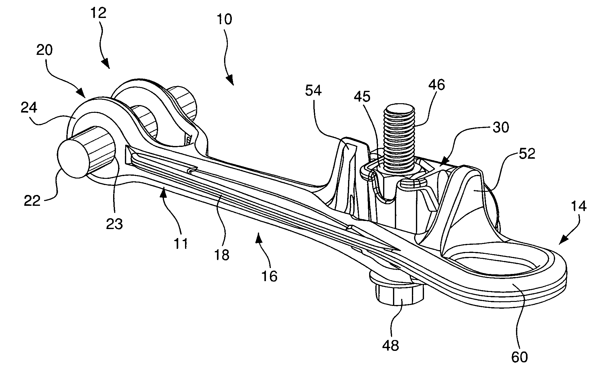
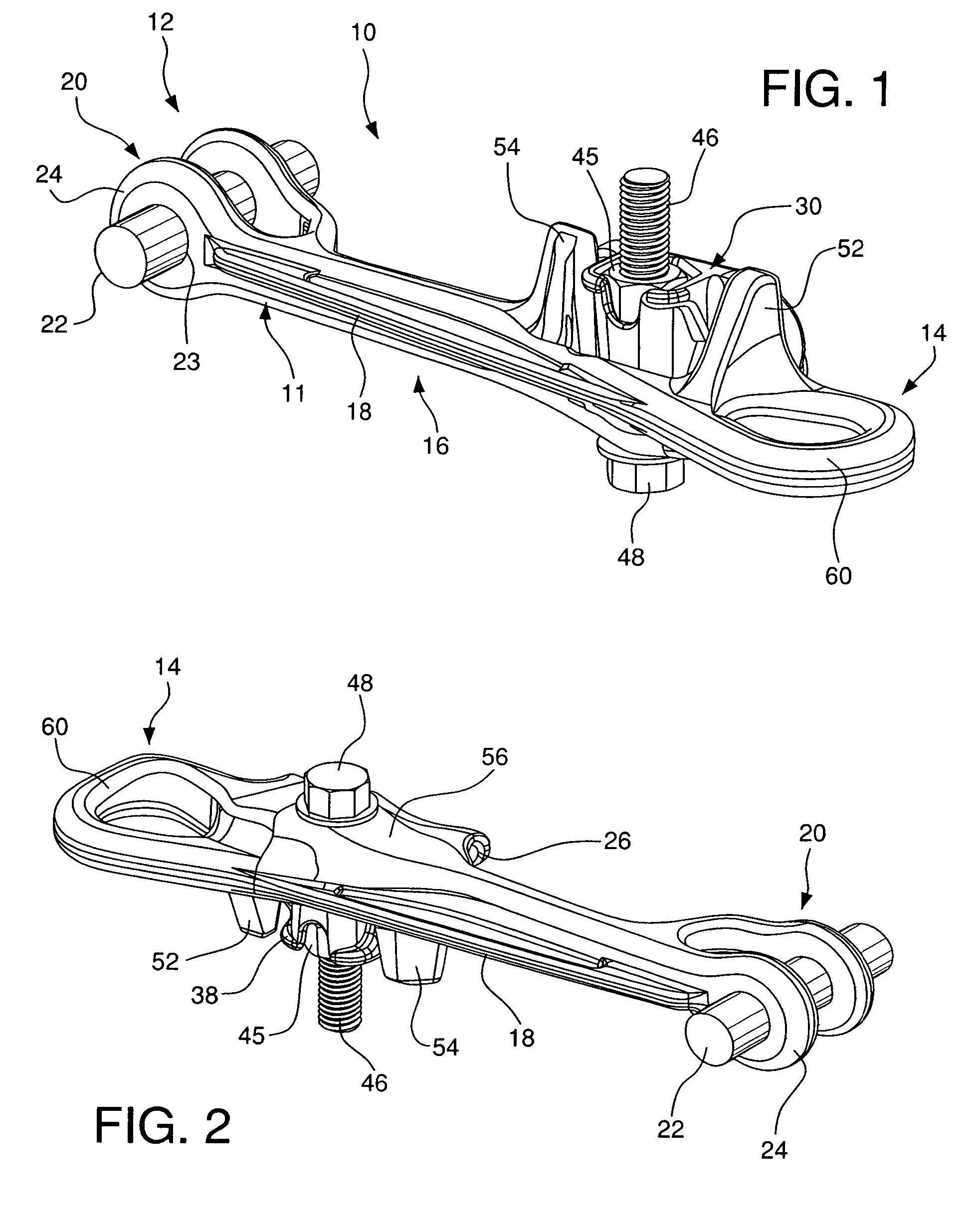
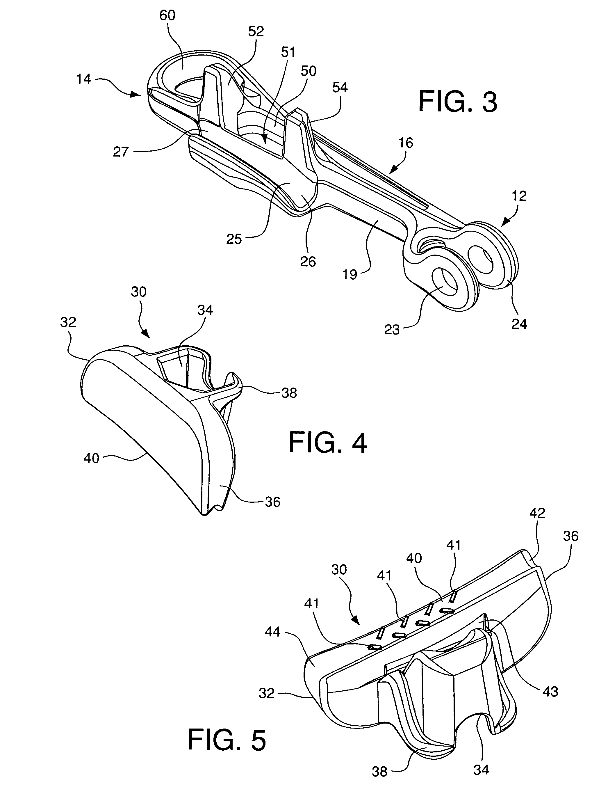
[0028]As seen in FIGS. 1-7, an anchor clamp 10 is illustrated for securing a cable. The anchor clamp 10 includes a main body 11 having a first end 12, a second end 14, a keeper 30 received in a pocket 50, and a biasing member 70 for counterbalancing a load between the keeper 30 and the retaining groove 26. A single bolt 46 received by the keeper 30 to attach the keeper 30 to the main body 11. The pocket 50 initiates a dynamic clamping action between the keeper 30 and the pocket 50 with the assistance of a biasing member 70 therebetween.

[0029]The anchor clamp 10 comprises a main body 11 defined by first end 12, opposing second end 14, and a middle section 16 extending therebetween. The first end 12 includes a clevis assembly 20 with a pin 22 threaded through coaxially aligned openings in a clevis bracket 24. The bracket 24 is substantially U-shaped for pivotal connection to a supporting structure (not shown). Each side of the bracket 24 is defined by a substantially circular shaped o...


PUM


Abstract

A single bolt deadend anchor clamp for gripping a cable includes a body having a clevis assembly at a first end and a sagging eye at an opposing second end. A middle body extends between the first and second ends, and includes a reinforcing rib. A pocket is adjacent the reinforcing rib for receiving a keeper inserted above the pocket. A biasing member is disposed between the pocket and the keeper for counterbalancing a load between the keeper and the retaining groove. The biasing member is preferably a spring including a cross bar and two sets of coils.

Description

CROSS REFERENCE TO RELATED APPLICATIONS[0001]This application claims the benefit of U.S. Provisional Application 60 / 720,654, filed Sep. 27, 2005. That application is hereby incorporated by reference in its entirety.FIELD OF THE INVENTION[0002]The present invention relates to a single bolt deadend anchor clamp designed to initiate a dynamic clamping action. More particularly, the invention relates to a wedge clamp comprising a body having a clevis assembly and a socket opposite one another, a middle body having a retaining groove for cable insertion, a pocket, a keeper, and a spring for counterbalancing a load between the keeper and the retaining groove.BACKGROUND OF THE INVENTION[0003]Conventional deadend anchor clamps are commonly used to secure a cable under tension, for example, an overhead electrical conductor. A deadend anchor clamp typically utilizes one or more U-bolts to clamp a keeper, which in turn applies a clamping pressure to the conductor. One drawback of conventional ...

Claims


Application Information

Patent Timeline
Patent Type & Authority Patents(United States)
IPC IPC(8): F16L3/00
CPCH02G7/056Y10T24/1955Y10T24/203
Inventor TAMM, CARL R.HAY, ROBERT G.
Owner HUBBELL INC
Why Eureka
Try Eureka